Drafting Merit Badge — Complete Digital Resource Guide
https://merit-badge.university/merit-badges/drafting/guide/
Introduction & Overview
Every bridge you cross, every building you enter, every phone in your pocket — none of it existed until someone drew it first. Drafting is the language engineers, architects, and designers use to turn ideas into reality. A precise drawing tells a builder exactly what to cut, where to weld, and how parts fit together — down to fractions of a millimeter. Without drafting, modern civilization simply could not be built.
This merit badge puts real drafting tools in your hands. You will format drawing sheets, create manual drawings with pencil and straightedge, design with computer-aided design (CAD) software, learn professional lettering, and discover how drafting drives real industries. By the end, you will know how to communicate a three-dimensional idea on a flat page so clearly that a stranger could build it.
Then and Now
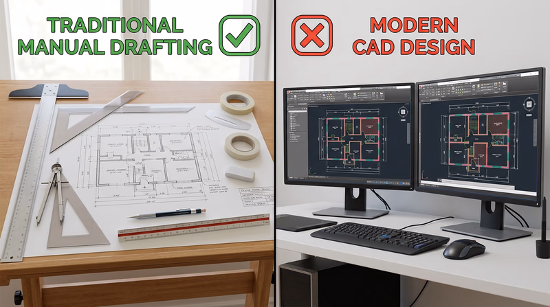
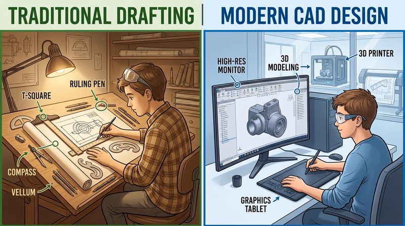
Then — Drawing by Hand, Building the World
For centuries, every structure and machine started as a hand-drawn plan. Ancient Egyptian builders used grids scratched on limestone to lay out the pyramids. Leonardo da Vinci filled notebooks with mechanical drawings so detailed that modern engineers have built working models from his 500-year-old sketches. During the Industrial Revolution, draftsmen worked at massive tilted drawing boards, using T-squares, triangles, compasses, and French curves to produce the blueprints for bridges, railroads, and skyscrapers. The term “blueprint” itself comes from a 19th-century chemical copying process that turned drawings white-on-blue.
- Tools: T-square, triangle, compass, protractor, ruling pen, mechanical pencil
- Mindset: Precision was life-and-death — a misplaced dimension on a bridge truss could cause collapse
Now — From Pixels to Products
Today, most professional drafting happens on a computer screen. CAD software like AutoCAD, SolidWorks, Fusion 360, and Revit lets designers create, modify, and share drawings in minutes that once took days. A 3D CAD model can be stress-tested digitally before any metal is cut, 3D-printed as a prototype overnight, or sent directly to a CNC machine that cuts parts to thousandths of an inch. Yet hand-drafting skills remain essential — engineers still sketch ideas on napkins, whiteboards, and notebooks before ever opening a CAD program.
- Tools: CAD software, 3D printers, CNC machines, laser cutters, tablets with styluses
- Mindset: Digital tools accelerate the process, but spatial thinking and drafting fundamentals still drive every great design
Get Ready! You are about to learn a skill that bridges art and engineering. Whether you dream of designing spacecraft, houses, circuit boards, or video game environments, drafting is the foundation. Sharpen your pencils and boot up your computer — it is time to draw.

Kinds of Drafting
Drafting shows up everywhere — from skyscrapers to smartphones. Here are the major branches you will encounter in this badge and beyond.
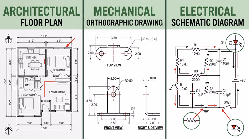
Architectural Drafting
Architectural drafters create the plans for buildings — floor plans showing room layouts, elevation drawings showing what a structure looks like from the outside, and detail drawings showing how walls, roofs, and foundations are assembled. If you have ever looked at a house plan or a blueprint for a school addition, you have seen architectural drafting. You will have the option to create an architectural drawing for Requirements 2 and 3.
Mechanical Drafting
Mechanical drafting covers machines, tools, vehicles, and manufactured parts. A mechanical drawing might show every dimension of a gear, the assembly of an engine, or the layout of a bicycle frame. Mechanical drafters use orthographic projection (showing an object from the top, front, and side) and isometric views (a 3D-looking view at an angle) to communicate how parts fit together.
Electrical Drafting
Electrical drafters produce schematic diagrams — drawings that use standardized symbols to represent components like resistors, capacitors, transistors, and switches. A schematic does not show what a circuit looks like physically; it shows how the components connect electrically. If you have ever built a circuit from a kit, the instruction diagram was an electrical schematic.
Civil Drafting
Civil drafters work on infrastructure projects — roads, bridges, dams, water systems, and land surveys. Their drawings include topographic maps showing elevation contours, site plans for construction projects, and profile views of roads and pipelines.
Structural Drafting
Structural drafting focuses on the bones of a building or bridge — the steel beams, concrete columns, and connections that hold everything up. A structural drawing details how loads flow through a structure and specifies the size and placement of every structural member.
3D Modeling & Parametric Design
Modern CAD goes beyond flat drawings into full 3D modeling. Parametric design tools like SolidWorks and Fusion 360 let you build a virtual 3D object, then automatically generate the 2D drawings from it. Change one dimension on the model, and every related drawing updates instantly. This is the direction the industry is heading.

Now that you understand the scope of drafting and why it matters, it is time to pick up your tools and get started with the fundamentals.
Req 1a — Rough Sketches & Paper Sizing
Before you lay a straightedge on a fresh sheet of drawing paper, you need to know what you are drawing and how big it needs to be. Professional drafters never jump straight to the final drawing — they start with a rough sketch. Think of it as a rehearsal: you figure out the layout, the scale, and the paper size before committing to the real thing.
Why Rough Sketches Matter
A rough sketch is a freehand drawing — no rulers, no precise measurements, just pencil on scrap paper. It serves three purposes:
- Layout planning — Where will the views go on the sheet? Will there be room for dimensions, notes, and a title block?
- Scale selection — What scale will make the drawing readable without wasting paper?
- Paper sizing — Based on the layout and scale, which standard paper size fits best?
Skipping the rough sketch is the fastest way to end up halfway through a drawing only to realize your floor plan does not fit on the sheet, or your dimensions are crammed so tightly together they become unreadable.
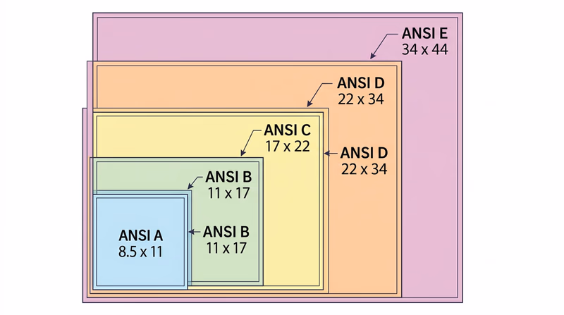
Standard Drawing Paper Sizes
Drafting paper comes in standard sizes defined by ANSI (American National Standards Institute). Each size is a specific width and height:
| Size | Dimensions (inches) | Common Use |
|---|---|---|
| A | 8.5 x 11 | Small details, schematics, simple parts |
| B | 11 x 17 | Small floor plans, mechanical parts, circuit diagrams |
| C | 17 x 22 | Medium architectural plans, assembly drawings |
| D | 22 x 34 | Large architectural plans, complex assemblies |
| E | 34 x 44 | Full building plans, large site plans |
For this merit badge, Size A (8.5 x 11) or Size B (11 x 17) will work for most projects. Size B gives you more room for dimensions and notes, which is especially helpful for architectural drawings.
How to Create Your Rough Sketch
Here is a step-by-step approach:
Decide what you are drawing. For Requirement 2, you will create a manual drawing (architectural, mechanical, or electrical). For Requirement 5 (as referenced in Requirement 1), you will create a lettering project. Make a rough sketch for each.
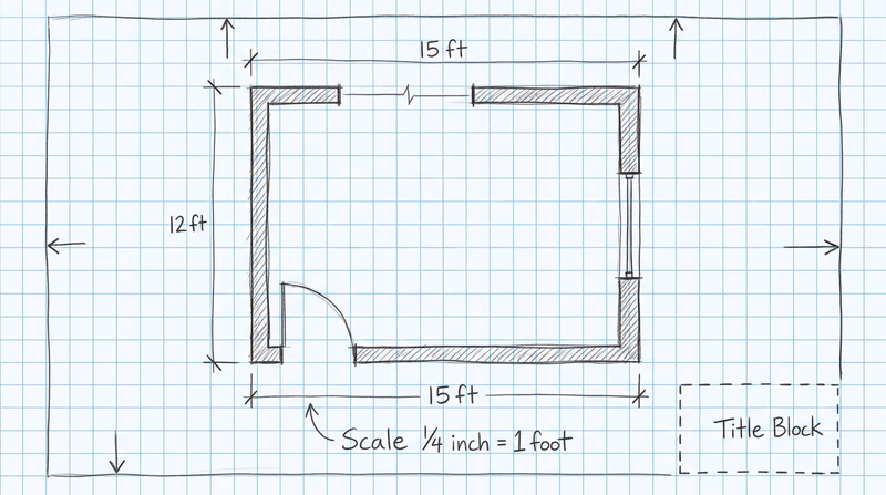
Estimate the object’s real-world dimensions. If you are drawing a floor plan of a room that is 12 feet by 15 feet, write those numbers down. If you are drawing a mechanical part that is 6 inches long, note that.
Choose a scale. Common scales include:
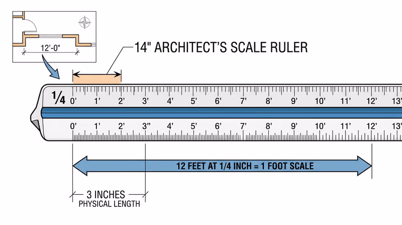
- Architectural: 1/4" = 1’-0" (a 12-foot wall becomes 3 inches on paper)
- Mechanical/engineering: Full size (1:1), half size (1:2), or double size (2:1)
- Electrical schematics: Usually not to scale — just make them clear and readable
Sketch the layout. On scrap paper, roughly draw where your views will sit on the sheet. Leave room for:
- A border (typically 1/2 inch on three sides, 1 inch on the left for binding)
- A title block (bottom right corner, about 4-5 inches wide by 1-2 inches tall)
- Dimensions and notes around each view
Pick your paper size. If the layout fits comfortably on A-size paper with room to spare, use A-size. If it is tight, step up to B-size.
Preparing for Both Projects
Remember: Requirement 1 asks you to format two sheets of paper — one for your manual drawing project (Requirement 2) and one for your lettering project (Requirement 6). Your rough sketches should account for both.
For the manual drawing project, your sketch should show where the drawing views, dimensions, notes, and bill of materials will go.
For the lettering project, your sketch should show how much text you plan to write and how large the lettering needs to be to fill the sheet attractively. Gothic lettering at 1/8-inch height takes up more space than you might expect — plan accordingly.
Engineering Drawing Standards — ASME Y14.1 The official ASME standard for drawing sheet sizes and formatting. This is the professional reference used in industry. Link: Engineering Drawing Standards — ASME Y14.1 — https://www.asme.org/codes-standards/find-codes-standards/y14-1-decimal-inch-drawing-sheet-size-formatNow that you have your rough sketches done and your paper sizes selected, it is time to set up those sheets with proper borders and a title block.
Req 1b — Title Block Lettering
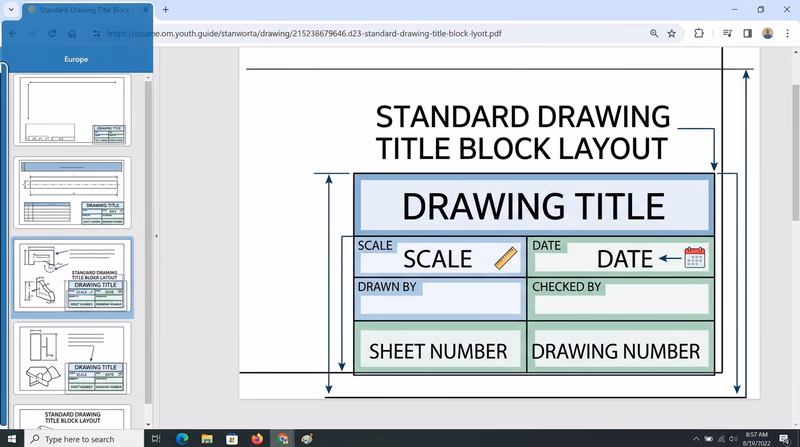
The title block is the professional ID card of every engineering drawing. It sits in the lower-right corner of the sheet and tells anyone who picks up the drawing exactly what they are looking at, who made it, when it was made, and at what scale. A drawing without a properly filled title block is like a letter without a return address — useless in a professional setting.
What Goes in a Title Block?
A standard title block contains these fields:
| Field | Purpose | Example |
|---|---|---|
| Drawing Title | Name of the object or project | “FIRST FLOOR PLAN” |
| Drawing Number | Unique identifier | “DWG-001” |
| Scale | Ratio of drawing to actual size | “1/4” = 1’-0"" or “1:2” |
| Date | When the drawing was completed | “03/04/2026” |
| Drawn By | Drafter’s name or initials | “JDS” |
| Checked By | Reviewer’s name or initials | (left blank or filled later) |
| Sheet Number | Which sheet in a set | “1 OF 2” |
| Material | What the part is made of | “6061 ALUMINUM” |
| Tolerances | Allowable variation | “±0.01” |
Not every title block uses all of these fields. For this merit badge, include at least the drawing title, your name, the date, the scale, and the drawing number.
Drawing the Border and Title Block
Before you letter anything, you need to draw the border and title block outline on your formatted sheet:
Border lines: Draw a border around the sheet, leaving a 1/2-inch margin on the top, bottom, and right sides. Leave a 1-inch margin on the left side (this extra space is for binding if the drawing set is stapled or hole-punched).
Title block outline: In the lower-right corner, draw a rectangle approximately 4.5 inches wide by 1.5 inches tall. Subdivide it with horizontal and vertical lines to create cells for each field.
Line weight: The border and title block outlines should be drawn with a thick, dark line. Use a softer pencil (like an HB or B) or press firmly with your mechanical pencil.
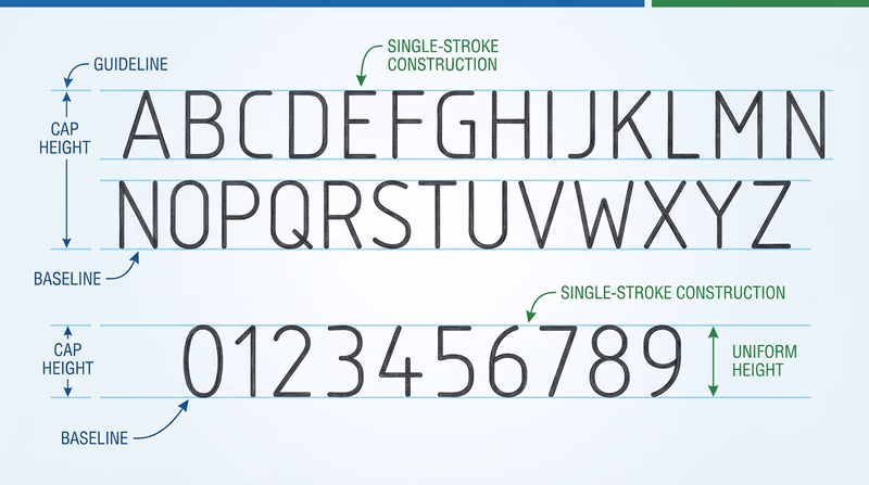
Gothic Lettering Basics
Gothic lettering — also called single-stroke lettering — is the standard lettering style for engineering drawings. It is designed to be clear, fast, and unmistakable. Every stroke is a single pass of the pencil, with no thick-and-thin variation.
You have two style choices:
Vertical Gothic — Letters stand straight up at 90 degrees. This is the most common style and generally easier for beginners.
Slant Gothic — Letters lean to the right at about 68 degrees from horizontal. Some drafters find this style more natural because it mimics cursive handwriting posture.
Pick one style and use it consistently throughout all your drawings. Mixing vertical and slant lettering on the same drawing looks unprofessional.
Lettering Technique
Good Gothic lettering comes down to consistent habits:
- Pencil choice: Use a sharp, medium-weight pencil (H or HB) for lettering. Too soft and the letters smear; too hard and they are faint.
- Stroke direction: Form vertical strokes from top to bottom, horizontal strokes from left to right. This produces the cleanest, most consistent lines.
- Spacing: Leave consistent space between letters. The spacing should look even to the eye, which means the actual distance varies — letters with open sides (like L and T) need slightly less space between them than letters with closed sides (like M and W).
- Uniformity: All letters of the same size should be exactly the same height. All vertical strokes should be exactly vertical (or at the same slant angle). This consistency is what makes professional lettering readable.
Practice Before the Final Sheet
Before lettering your actual title blocks, practice on scrap paper:
- Draw sets of horizontal guidelines at 1/8-inch spacing
- Letter the full alphabet (uppercase only — Gothic lettering uses ALL CAPS)
- Letter the numerals 0 through 9
- Practice your name, today’s date, and a sample drawing title
- Check that your letters are uniform in height and spacing
Once your lettering is consistent and confident, fill in the title blocks on both formatted sheets — the one for your manual drawing (Requirement 2) and the one for your lettering project (Requirement 6).
Title Block Completion Checklist
Verify before moving on- Border drawn with correct margins (1 inch left, 1/2 inch other sides).
- Title block rectangle drawn in the lower-right corner.
- Title block subdivided into labeled cells.
- All lettering uses consistent Gothic style (vertical OR slant, not mixed).
- Guidelines visible or lightly erased.
- Text is legible, uniform in height, and dark enough to reproduce clearly.
- Both sheets (manual drawing and lettering project) are formatted and lettered.
With your sheets formatted, bordered, and titled, you are ready for the main event — creating your manual drafting project.
Req 2 — Choose Your Drawing Type
This is the centerpiece of the merit badge — a hand-drawn technical drawing created with pencil, straightedge, and scale. You will choose one of three drawing types: architectural, mechanical, or electrical. Read through all three options below, then pick the one that interests you most and matches your available tools.
Remember: you only need to complete ONE of these options.
Option A: Architectural Drawing
An architectural drawing communicates the design of a building or structure. The most common type for this badge is a floor plan — a top-down view showing walls, doors, windows, and room labels as if you sliced the building horizontally about four feet above the floor.
What you will need:
- Architect’s scale (triangular ruler with multiple scales)
- T-square or parallel straightedge
- Triangles (30-60-90 and 45-45-90)
- Your formatted sheet from Requirement 1
Key elements to include:
- Walls drawn to scale (typically shown as parallel lines with hatching or solid fill)
- Doors shown as arcs indicating the swing direction
- Windows shown as breaks in the wall with parallel lines
- Dimensions showing actual room sizes, wall thicknesses, and overall building dimensions
- Room labels identifying each space
- Notes calling out materials, finishes, or construction methods
- A bill of materials listing at least three raw materials (e.g., 2x4 lumber, drywall, concrete)
Using an architect’s scale:
An architect’s scale has multiple scales printed on its edges. The most common for residential drawings is 1/4" = 1’-0", which means every 1/4 inch on your drawing represents 1 foot in real life. To draw a 12-foot wall, you would measure 3 inches on your paper using the 1/4-inch scale edge.
Option B: Mechanical Drawing
A mechanical drawing shows a physical object — a tool, a device, a bracket, a toy — with enough detail that someone could manufacture it. The two main styles are:
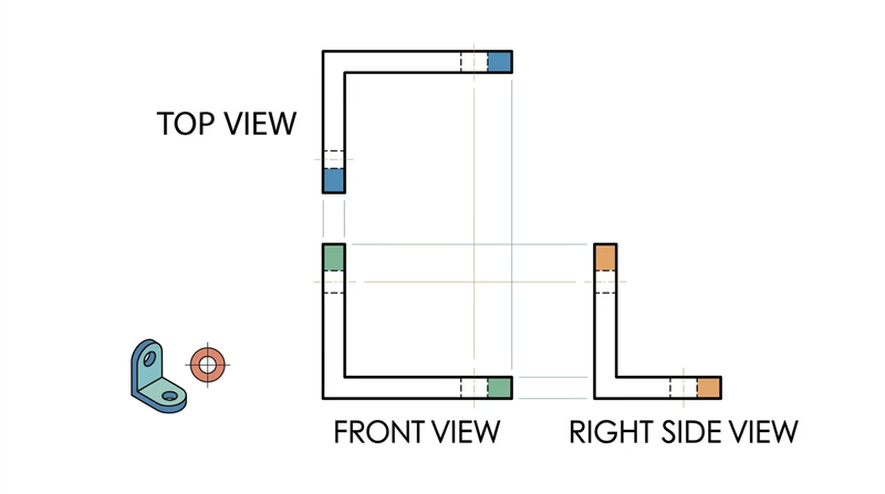
Orthographic (Third-Angle) Projection — Shows the object from three views: front, top, and right side. Each view shows the object as if you are looking straight at it from that direction. This is the standard for manufacturing drawings in the United States.
Isometric Drawing — Shows the object in a 3D-looking view where all three axes (width, height, depth) are drawn at equal angles (30 degrees from horizontal). Isometric drawings give a good visual sense of the object’s shape but are not used for dimensioning in manufacturing.
Good project ideas:
- A simple hand tool (hammer, wrench, screwdriver)
- A bookend, phone stand, or shelf bracket
- A game piece or puzzle
- A birdhouse or toolbox
Key elements to include:
- At least two orthographic views (front and top, or front and side) OR one isometric view
- Dimensions with proper dimension lines, extension lines, and arrowheads
- Notes on materials and manufacturing methods
- A bill of materials for at least three components or raw materials
- A section view if the object has interior features that are not visible from the outside
Option C: Electrical Schematic
An electrical schematic is a diagram that shows how electronic components connect to form a circuit. Unlike architectural and mechanical drawings, schematics are usually not drawn to scale — the layout is arranged for clarity, not to represent physical positions.
Standard symbols you will use:
| Component | Symbol Description |
|---|---|
| Resistor | Zigzag line |
| Capacitor | Two parallel lines with a gap |
| Inductor | Series of loops |
| Diode | Triangle pointing at a line |
| Transistor | Circle with three leads (base, collector, emitter) |
| Battery | Alternating long and short parallel lines |
| Ground | Three horizontal lines decreasing in length |
| Switch | Break in the line with a hinged connector |
Good project ideas:
- A simple AM radio circuit
- An LED flashlight circuit with resistor and switch
- A basic amplifier circuit
- A 555 timer circuit (used in thousands of electronics projects)
Key elements to include:
- All components drawn with standard IEEE/ANSI symbols
- Component labels (R1, R2, C1, etc.)
- Component values (10kΩ, 100μF, etc.)
- Connection dots at wire junctions
- Power supply connections (V+ and ground)
- A bill of materials listing all major components with their values and quantities
Which Option Should You Choose?
| Option | Best For | You Will Need |
|---|---|---|
| A — Architectural | Scouts interested in buildings, construction, interior design | Architect’s scale, tape measure for measuring real rooms |
| B — Mechanical | Scouts interested in machines, manufacturing, 3D objects | Engineer’s scale, an interesting object to draw |
| C — Electrical | Scouts interested in electronics, circuits, radio, robotics | Reference for standard symbols, a circuit to draw |
Talk with your counselor about which option fits your interests. Whichever you choose, your manual drawing for Requirement 2 should be on the formatted sheet you prepared in Requirement 1, with all title block information filled in.
In Requirement 3, you will create a similar drawing — but this time using CAD software instead of pencil and paper. Completing both gives you a direct comparison of manual and digital drafting.
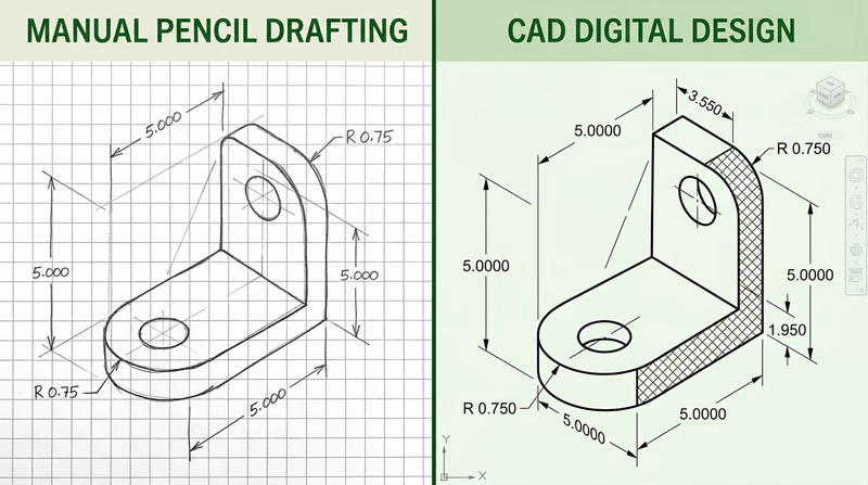
Req 3 — CAD Design
Now you shift from pencil and paper to a computer screen. Computer-aided design (CAD) software lets you create precise drawings using a mouse, keyboard, and digital tools that replace your T-square, triangles, and compass. You will choose one of the same three drawing types — architectural, mechanical, or electrical — and produce a CAD version.
Remember: you only need to complete ONE of these options. You may choose the same type you drew by hand in Requirement 2 (which makes comparison easier) or try a different type to broaden your experience.
Option A: Architectural CAD Drawing
In CAD, you draw at full scale — a 12-foot wall is drawn as 12 feet in the software. The program handles scaling when you print or export the drawing. This is one of the biggest advantages of CAD over hand drawing: you never have to calculate scale conversions while you draw.
Architectural CAD features to use:
- Layers — Put walls, dimensions, text, and symbols on separate layers so you can control what is visible
- Snap and grid — Lock your cursor to grid points for precise placement
- Dimension tools — The software calculates and displays measurements automatically
- Hatch patterns — Fill wall sections with patterns to indicate materials (concrete, insulation, etc.)
- Blocks/symbols — Insert pre-made door, window, and fixture symbols from a library
Option B: Mechanical CAD Drawing
Mechanical CAD shines when you need precise geometry and easy modifications. Drawing a circle in CAD is a matter of clicking a center point and typing a radius. Drawing that same circle by hand requires a compass, a steady hand, and hope that you do not smudge it.
Mechanical CAD features to use:
- Precise input — Type exact coordinates and dimensions instead of measuring with a ruler
- Mirror and array — Create symmetrical features or patterns of holes instantly
- Section views — Cut through your object to show interior details
- Automatic BOM — Some programs can generate a bill of materials from your drawing data
Option C: Electrical CAD Schematic
Electrical schematics are where CAD truly outshines hand drawing. Schematic capture software includes libraries of standard component symbols — resistors, capacitors, transistors, integrated circuits — that you simply drag into place and connect with wires. The software can also check your circuit for errors, generate netlists for circuit board layout, and produce a bill of materials automatically.
Electrical CAD features to use:
- Symbol libraries — Drag standard IEEE/ANSI component symbols onto your schematic
- Wire routing — Draw connections between components with automatic corner handling
- Net labels — Name connections (like “VCC” or “GND”) so the software tracks them even if wires are not visually connected
- BOM export — Generate a bill of materials directly from the schematic
Choosing CAD Software
You have several options for CAD software, ranging from free to professional-grade. Here are the most accessible choices for a Scout working on this badge:
Free Options
Onshape (Free Education Plan) Cloud-based 3D CAD — runs in a web browser, no installation required. Free for students and educators. Excellent for mechanical drawings. Link: Onshape (Free Education Plan) — https://www.onshape.com/en/education/ LibreCAD Free, open-source 2D CAD software. Works on Windows, Mac, and Linux. Good for architectural and mechanical 2D drawings. Link: LibreCAD — https://librecad.org/ KiCad Free, open-source electronics CAD for schematic capture and PCB layout. Industry-quality tool used by professionals and hobbyists. Link: KiCad — https://www.kicad.org/ Tinkercad Free browser-based 3D design and circuit simulation tool from Autodesk. Great for beginners — includes both 3D modeling and circuit design. Link: Tinkercad — https://www.tinkercad.com/Professional Tools (Free Student Versions)
Autodesk Fusion (Free Personal Use) Professional 3D CAD/CAM software with a free version for personal, non-commercial use. Parametric modeling, 2D drawings, and more. Link: Autodesk Fusion (Free Personal Use) — https://www.autodesk.com/products/fusion-360/personal AutoCAD (Free Student License) The industry-standard 2D/3D CAD software. Free one-year license for students. Link: AutoCAD (Free Student License) — https://www.autodesk.com/education/free-software/autocad
CAD Drawing Essentials
Regardless of which software and drawing type you choose, every CAD drawing for this badge should include:
CAD Drawing Checklist
Must-haves for your Requirement 3 drawing- Drawing created in CAD software (not hand-drawn and scanned).
- Correct scale indicated in the title block.
- Proper dimensions with dimension lines, extension lines, and values.
- Title block filled in with all relevant information.
- Notes explaining materials, construction methods, or component values.
- Bill of materials (for architectural and mechanical options).
- Clean, professional appearance with consistent line weights and text sizes.
When you finish your CAD drawing, save it in the software’s native format and also export a PDF. You will present both your manual and CAD drawings to your counselor in the next requirement.
Req 4 — Review & Revision Process
This requirement introduces you to one of the most important processes in professional drafting: the review-and-revise cycle. No drawing ships without being checked, marked up, corrected, and documented. This is how errors get caught before anything gets built.
Part A: Presenting Your Drawings for Review
In the professional world, a finished drawing goes to a checker — a senior drafter or engineer who reviews it for errors, omissions, and clarity. The checker marks corrections directly on a copy of the drawing using a red pencil or pen. This marked-up copy is called a redline.
Redlines are not punishment — they are a normal and expected part of the process. Even experienced drafters produce drawings that need corrections. The redline review catches mistakes before they become expensive construction or manufacturing errors.
What your counselor may redline:
- A missing or incorrect dimension
- A feature to add, remove, or modify
- A bill of materials quantity change
- A note that needs clarification
- A scale error or inconsistency
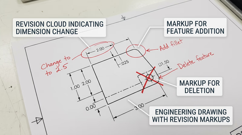
What Redline Markups Look Like
Professional redlines use standard markup conventions:
| Markup | Meaning |
|---|---|
| Cloud/bubble around an area | Something inside needs attention |
| Crossed-out dimension with new number | Change this measurement |
| Arrow with note | Add something at this location |
| X through a feature | Delete this feature |
| Delta triangle (Δ) | Revision identifier |
| “RFI” notation | Request for information — the checker has a question |
Part B: Making Corrections and Adding Revision Tracking
Once you receive your redlined drawings back from your counselor, it is time to make the corrections. But simply fixing the error is not enough — you must also document the revision so anyone looking at the drawing in the future can see what changed.
How to Process a Redline
Read all markups first. Go through the entire redlined drawing before making any changes. Understand the full scope of corrections needed.
Make the corrections. On your manual drawing, carefully erase and redraw the corrected features. In CAD, modify the geometry, dimensions, or notes as indicated.
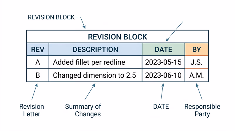
Add a revision marker. Place a small triangle with a revision letter (A, B, C, etc.) next to each corrected area on the drawing. This is called a revision triangle or delta symbol. It tells the reader “something changed here.”
Add a revision block. In the upper-right corner of the drawing (or adjacent to the title block), add a small table called a revision block:
| Rev | Description | Date | By |
|---|---|---|---|
| A | Changed wall thickness per redline | 03/04/2026 | JDS |
The revision block is a permanent record of every change made to the drawing after its initial release.
- Update the title block. Some drafters update the date in the title block to reflect the latest revision. Others leave the original date and let the revision block tell the revision story. Follow your counselor’s preference.
Revision Processing Checklist
Steps to complete Requirement 4b- Read all redline markups before starting corrections.
- Make every correction indicated by the redline.
- Place a revision triangle (with letter) next to each changed area.
- Add a revision block with revision letter, description, date, and initials.
- Verify the correction matches the redline intent — do not over-correct or under-correct.
- Present the revised drawing to your counselor for final review.
Why Revision Tracking Matters
Imagine a bridge is being built from a set of drawings. The steel fabricator has the original Rev A drawings. The engineer discovers a beam size needs to change and issues Rev B. If the fabricator does not receive Rev B — or cannot tell which parts of the drawing changed — they might build with the wrong beam size.
Revision tracking prevents this. Every changed drawing gets a new revision letter, every changed feature gets a triangle, and every revision block entry explains what happened. In industries like aerospace and medical devices, revision control is required by law.
The experience you are getting here — presenting a drawing, receiving feedback, making corrections, and documenting changes — mirrors exactly what happens in a professional drafting office. It is a cycle that repeats throughout the life of any project.
ASME Y14.35 — Revision of Engineering Drawings The official ASME standard for revision tracking on engineering drawings. This is the professional reference used across industries. Link: ASME Y14.35 — Revision of Engineering Drawings — https://www.asme.org/codes-standards/find-codes-standards/y14-35m-revision-engineering-drawings-associated-documentsNow you have completed both a manual and a CAD drawing, and you have gone through the professional review-and-revise process. Next, you will reflect on how these two approaches compared.
Req 5 — Manual vs. CAD Discussion
You have now created a drawing by hand and a drawing with CAD. You have also gone through the redline and revision process. This requirement asks you to step back and think critically about the differences between these approaches. Your counselor wants to hear your personal observations — not a memorized list of bullet points.
Reflecting on Your Experience
Think about these questions as you prepare for your discussion. Consider what you actually experienced, not just what you read about:
Speed and setup:
- How long did the manual drawing take compared to the CAD drawing?
- Which method had a steeper learning curve for you?
- How much time did you spend on setup (formatting paper, opening software, configuring settings) versus actual drawing?
Precision and accuracy:
- Which drawing turned out more precise? Why?
- Did you make dimensional errors with either method? How easy were they to catch?
- How did snapping and automatic dimensioning in CAD compare to measuring with a scale by hand?
Making changes:
- Think back to Requirement 4 — when you received redline corrections, which drawing was easier to revise?
- On the manual drawing, did you have to erase and redraw? How clean was the result?
- In CAD, could you simply modify the geometry and have dimensions update automatically?
Key Benefits of CAD
Here are some widely recognized benefits of CAD that you should be prepared to discuss, supported by your own experience:
Precision Without Skill Decay
In manual drafting, precision depends on your hands. A tired drafter at the end of a long day draws less accurately than a fresh one in the morning. CAD does not get tired. Every line is mathematically exact, every dimension is calculated by the software, and every circle is a perfect circle.
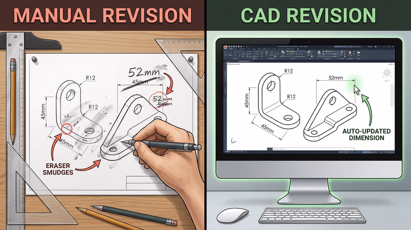
Easy Revisions
This is often the single biggest advantage. In manual drafting, changing a wall thickness means erasing, redrawing, and re-dimensioning — and hoping the erased area does not leave ghost marks. In CAD, you select the wall, type a new thickness, and every related dimension updates. The revision you made in Requirement 4 probably demonstrated this difference clearly.
Reusability
A door symbol drawn once in CAD can be saved as a block and inserted into hundreds of future drawings. A title block template can be reused for every project. Manual drafting requires redrawing common elements every time.
Collaboration and Sharing
CAD files can be emailed, stored in the cloud, and worked on by multiple people simultaneously. Manual drawings must be physically transported or scanned.
Automatic Documentation
CAD software can automatically generate bills of materials, calculate areas, count components, and produce reports — tasks that require manual counting and calculation with hand drawings.
Software Discussion Points
Your counselor will want to know what software you used and what other options exist. Here is a framework for that discussion:
What You Used
Be prepared to describe:
- The name and version of the software
- Whether it was free, student-licensed, or paid
- What you liked and disliked about it
- Whether it was 2D-only, 3D, or both
Other Software Options
When discussing alternatives, organize them by category:
2D Drafting (traditional CAD):
- AutoCAD — The industry standard for 2D drafting since 1982
- LibreCAD — Free, open-source 2D CAD
- DraftSight — Professional 2D CAD with a free version
3D Parametric Modeling:
- SolidWorks — Widely used in mechanical engineering and manufacturing
- Fusion 360 (now Autodesk Fusion) — Free for personal use, combines CAD/CAM/CAE
- Onshape — Cloud-based, runs in a browser, free for education
- Inventor — Autodesk’s parametric modeling tool
Electrical/Electronics:
- KiCad — Free, open-source schematic and PCB design
- EAGLE — PCB design tool (now part of Autodesk Fusion)
- LTspice — Free circuit simulation software
Architectural (BIM):
- Revit — Building Information Modeling software from Autodesk
- SketchUp — 3D modeling tool popular for architectural visualization
- FreeCAD — Free, open-source parametric 3D modeler
Discussion Prep Checklist
Points to cover with your counselor- How your manual and CAD drawings differed in process and result.
- At least three specific benefits of CAD that you experienced firsthand.
- How the revision process (Requirement 4) was easier or harder in each method.
- The name of the software you used and why you chose it.
- At least two or three alternative software options you are aware of.
- Your personal opinion on when manual drafting is still useful versus when CAD is clearly better.
When Manual Drafting Still Wins
Do not leave your counselor with the impression that manual drafting is obsolete. It is not. Engineers and architects still sketch by hand every day — on whiteboards, in notebooks, on napkins during lunch meetings. Hand sketching is faster for brainstorming, requires no computer, and develops your spatial thinking in ways that CAD cannot replicate. The rough sketches you made in Requirement 1a are a perfect example of where hand drawing excels.
The real takeaway: manual and CAD drafting are not competitors — they are partners. A skilled drafter uses both.
Req 6 — Lettering Your Opinion
This requirement brings together two skills: the Gothic lettering you practiced in Requirement 1b and the understanding of CAD benefits you developed in Requirements 2 through 5. You will hand-letter a short essay — in proper Gothic lettering, without templates — on the formatted sheet you prepared at the start of the badge.
Planning Your Written Piece
Before you start lettering on your final sheet, plan your content carefully. You need to address three things:
- Pick an industry — aerospace, electronics, manufacturing, architectural, or another industry that interests you
- Name the most important CAD benefit for that industry — not a generic benefit, but one that matters specifically in your chosen field
- Support your opinion with examples from your own experience in Requirements 2 through 5
CAD Benefits by Industry
Here are some industry-specific angles to consider. Think about which one resonates with your experience:
Aerospace — In aerospace, every gram matters and tolerances are measured in thousandths of an inch. CAD allows engineers to simulate stress, airflow, and weight before a single part is manufactured. The ability to digitally test a wing design before building it saves billions of dollars and, more importantly, lives.
Electronics — Modern circuit boards pack thousands of components into spaces smaller than a playing card. CAD software can automatically check for electrical conflicts, route traces between components, and generate manufacturing files that go directly to circuit board fabrication machines. Hand-drawing a smartphone’s circuit board would be physically impossible.
Manufacturing — CAD models can be sent directly to CNC machines, 3D printers, and laser cutters. This CAD-to-machine pipeline eliminates the step where a machinist interprets a drawing — the machine reads the digital file and cuts exactly what was designed.
Architectural — Building Information Modeling (BIM) goes beyond flat drawings to create a complete digital twin of a building. Architects, structural engineers, mechanical engineers, and electrical engineers all work on the same model. If an HVAC duct conflicts with a structural beam, the software detects the clash before construction begins.
Lettering Execution
Now that you know what you want to say, it is time to letter it on your formatted sheet. Here is how to approach this project:
Step 1: Draft Your Text on Scratch Paper
Write out your explanation in regular handwriting first. Aim for 3-5 sentences — enough to state your opinion, identify the industry, and support your reasoning with your own experience. Count the words so you can estimate how much space you need.
Step 2: Plan the Layout
On a separate piece of scrap paper, figure out:
- How many lines of text you will need
- What letter height to use (1/8 inch is standard for body text; 3/16 or 1/4 inch for a title)
- How the text will be centered or aligned on the sheet
- Where to place a title (e.g., “CAD IN AEROSPACE MANUFACTURING”)
Step 3: Draw Guidelines
On your formatted sheet, lightly draw horizontal guidelines with a hard pencil (4H or 6H). Space them according to your chosen letter height. These guidelines ensure uniform lettering.
Step 4: Letter the Final Text
Using either vertical or slant Gothic lettering (the same style you used for your title blocks), carefully letter your explanation. Take your time. If you make a mistake, carefully erase and re-letter — clean corrections are expected.
Lettering Project Checklist
Quality checks for your finished piece- Written on the formatted sheet from Requirement 1 (with border and title block).
- All lettering is single-stroke Gothic — vertical OR slant, consistent throughout.
- No templates or lettering guides used.
- Title block information is filled in completely.
- Text clearly identifies one industry.
- Text names a specific CAD benefit for that industry.
- Text references your personal experience from Requirements 2–5.
- Letters are uniform in height and spacing.
- Guidelines are either visible or lightly erased.
- Text is dark enough to read clearly and photocopy well.

Sample Structure (Not Sample Content)
Here is how you might structure your explanation — but use your own words and your own experience:
Title line (larger lettering): Name of the industry and topic
Body (standard lettering): State which CAD benefit you consider most important for this industry. Explain why it matters in that specific industry. Reference something from your own manual vs. CAD experience that illustrates the benefit. Conclude with a sentence about why this benefit matters for the future.
CAD in Industry — Autodesk Overview Overview of how CAD software is used across architecture, engineering, construction, and manufacturing industries. Link: CAD in Industry — Autodesk Overview — https://www.autodesk.com/solutions/cad-softwareYour lettering project is the last drawing deliverable for this badge. Next, you will explore how drafting works in the real world — either by visiting a workplace or researching the trade.
Req 7 — Workplace Visit or Research
This requirement connects your badge work to the professional drafting world. You will choose one of two paths: visiting a workplace where drafting happens, or researching the history and evolution of drafting tools and media. Read through both options and pick the one that works best for your situation.
Remember: you only need to complete ONE of these options.
Option A: Visit a Drafting Workplace
A workplace visit brings everything you have learned in this badge to life. You will see how professional drafters and engineers use the same skills — drawing, dimensioning, revising — in a real business setting. The requirement asks you to investigate three specific areas during your visit:
Sub-requirement 7a(1): Manual vs. CAD in the Workplace
Most modern workplaces use CAD almost exclusively, but you might be surprised to find manual skills still in play — especially during design brainstorming, field sketches, or in shops that maintain older equipment with legacy drawings.
Questions to ask:
- What percentage of your drafting is done with CAD versus by hand?
- What CAD software do you use? Did you evaluate other options before choosing it?
- Do your drafters ever sketch by hand? In what situations?
- How did the transition from manual to CAD happen here?
Sub-requirement 7a(2): Who Uses the Drawings?
Drawings are communication tools — they carry information from the designer to the builder, installer, inspector, and maintenance crew. Understanding who reads the drawings helps you understand why accuracy and clarity matter so much.
Questions to ask:
- Who are the main users of the drawings your team produces?
- How do drawings get transmitted to the people who need them — paper, PDF, shared CAD files?
- How does the drafting team work with engineers, architects, or project managers?
- What happens when someone in the field has a question about a drawing?
Sub-requirement 7a(3): Drafting’s Role in the Business
This question gets at the big picture — how does drafting fit into the company’s overall mission? In some businesses, drafting is the core product (architecture and engineering firms sell drawings). In others, drafting supports manufacturing, construction, or maintenance.
Questions to ask:
- Could this business operate without a drafting department? Why or why not?
- How has drafting improved the quality or speed of your products/services?
- What would happen if a drawing contained a significant error that was not caught?

Workplace Visit Prep
Be ready before you arrive- Arrange the visit through your counselor or a parent/guardian — do not just show up.
- Write down your questions in advance so you do not forget anything.
- Bring a notebook to record answers and observations.
- Wear appropriate clothing (collared shirt, closed-toe shoes if visiting a shop floor).
- Thank your hosts at the end of the visit and follow up with a written thank-you note.
Option B: Research the Drafting Trade
If a workplace visit is not feasible, this option lets you research the history and evolution of drafting tools and media. You will investigate three topics:
Sub-requirement 7b(1): Evolution of Drafting Tools
The history of drafting tools stretches back thousands of years. Here are some starting points for your research:
Historical tools:
- Compass and straightedge — Used since ancient Greece, still fundamental today
- T-square — A long straightedge that slides along the edge of a drafting board to draw horizontal lines. Once the most essential drafting tool.
- Triangles — 30-60-90 and 45-45-90 triangles used with a T-square to draw angled lines
- French curve — A plastic template with complex curves for drawing smooth non-circular arcs
- Ruling pen — A pen with an adjustable gap between two blades, used for drawing ink lines of consistent width
- Parallel rule — A straightedge mounted on cables across a drafting board, replacing the T-square
Tools still in use: Mechanical pencils, architect’s and engineer’s scales, compasses, erasers, and triangles are still used for hand sketching and markup.
Tools becoming obsolete: Ruling pens, lettering guides, drafting machines (pantograph-style devices mounted to drawing boards), and large-format light tables have been largely replaced by CAD.
Sub-requirement 7b(2): Drawing Media Through History
Historical media:
- Vellum — Translucent drafting paper that allowed blueprinting (light-sensitive copying)
- Mylar — Plastic film that replaced vellum; more durable and dimensionally stable
- Linen — Starched cotton fabric used for permanent ink drawings before plastic films existed
- Blueprints — A chemical reproduction process using light-sensitive paper that produced white lines on a blue background. The term “blueprint” is still used colloquially even though the process is nearly extinct.
- Diazo prints — Replaced blueprints; produced blue or black lines on white paper using ammonia fumes
Modern media: CAD files stored on hard drives, cloud servers, and version-controlled repositories. Drawings are shared as PDFs, plotted on large-format inkjet printers, or viewed directly on screens and tablets at job sites.
Sub-requirement 7b(3): New Media and New Uses
The shift from paper to digital has not just changed how drawings are made — it has changed what drawings can do:
- 3D models replace flat 2D drawings in many workflows, allowing virtual walkthroughs and interference checking
- BIM (Building Information Modeling) embeds cost, schedule, and material data directly into the 3D model
- VR and AR let designers and clients walk through buildings before they are built, using headsets or tablet overlays
- Direct-to-machine output sends CAD geometry to CNC mills, 3D printers, and laser cutters without a human interpreting a drawing
- Cloud collaboration allows teams in different cities or countries to work on the same model simultaneously
Which Option Should You Choose?
| Option | Best For | Requires |
|---|---|---|
| A — Workplace Visit | Hands-on learners who want to see real drafting in action | Access to a business with a drafting or engineering department |
| B — Research | Scouts interested in history and technology evolution | Library access, internet research, curiosity |
Discuss with your counselor which option fits your situation best.
You are almost done with the Drafting merit badge. One requirement remains — exploring drafting as a career.
Req 8 — Drafting Career Exploration
Drafting skills open doors to careers that most people do not even know exist. The ability to read, create, and modify technical drawings is valuable across dozens of industries — from designing skyscrapers to engineering spacecraft. This requirement asks you to explore three career paths and dive deep into one.
Step 1: Identify Three Career Opportunities
Here are careers that directly use drafting skills and knowledge. Choose three that interest you:
Design and Drafting Careers
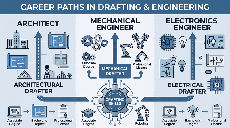
Architectural Drafter — Creates detailed drawings for buildings, from residential homes to commercial high-rises. Works closely with architects to turn design concepts into construction documents.
Mechanical Drafter — Produces drawings for manufactured products, machinery, and mechanical systems. Found in automotive, aerospace, consumer products, and industrial equipment companies.
Civil Drafter — Draws plans for roads, bridges, water systems, and land development projects. Works with civil engineers and surveyors.
Electrical/Electronics Drafter — Creates wiring diagrams, circuit board layouts, and electrical system plans for buildings, vehicles, and electronic devices.
Engineering Careers
Mechanical Engineer — Designs and analyzes mechanical systems. Uses CAD extensively for design, simulation, and documentation.
Civil Engineer — Plans infrastructure projects. Every road, bridge, and water treatment plant starts as a set of drawings.
Aerospace Engineer — Designs aircraft, spacecraft, and satellites. CAD and 3D modeling are essential daily tools.
Electrical Engineer — Designs circuits, power systems, and electronic devices. Uses schematic capture and PCB layout software.
Related Careers
Architect — Designs buildings and oversees construction. Architecture combines artistic vision with technical drafting.
Industrial Designer — Designs consumer products (furniture, appliances, tools) with a focus on form, function, and user experience. Heavy CAD use.
Surveyor — Measures and maps land boundaries and features. Survey data feeds directly into civil engineering drawings.
BIM Manager — Oversees Building Information Modeling processes for construction firms. A growing career that combines drafting, technology, and project management.
Step 2: Research One Career in Depth
Pick the career that interests you most and dig into the details. Your counselor will want you to address each of these areas:
Training and Education
- What degree or certificate is required? (Associate degree, bachelor’s degree, trade school certificate)
- What subjects should you study in high school to prepare? (Math, physics, computer science, art)
- Are there specific college programs or technical schools known for this field?
Certifications
- Are professional certifications required or recommended?
- Examples: ADDA (American Design Drafting Association) offers the Certified Drafter (CD) credential. Engineers typically need a PE (Professional Engineer) license. Architects need to pass the ARE (Architect Registration Examination).
- What does certification involve — exams, experience requirements, continuing education?
Experience
- How do people typically enter this career — internships, apprenticeships, entry-level positions?
- How many years of experience are needed to become fully proficient?
- Is a portfolio of work important for getting hired?
Expenses
- What does the education cost? (Tuition for a 2-year vs. 4-year program)
- Are there software costs? (Some employers provide software; freelancers must purchase their own)
- Are there professional membership or certification exam fees?
Employment Prospects
- Is this career growing, stable, or declining?
- Where are the jobs concentrated geographically?
- Are remote work opportunities available?
Salary and Advancement
- What is the typical starting salary?
- What can experienced professionals earn?
- What are the advancement paths? (Senior drafter, lead designer, project manager, engineering manager)

Career Research Checklist
What to cover in your discussion with your counselor- Three career opportunities identified that use drafting skills.
- One career researched in depth.
- Education and training requirements described.
- Certification or licensing requirements identified.
- Typical entry path and experience needs explained.
- Education and startup costs estimated.
- Employment outlook assessed (growing, stable, or declining).
- Starting and experienced salary ranges found.
- Advancement opportunities and career goals described.
- Your personal interest level — would you consider this career?
Connecting This to Your Future
You do not need to decide your career at 14. But knowing that drafting skills lead to well-paying, creative, in-demand careers is valuable information. Whether you end up designing buildings, engineering cars, laying out circuit boards, or doing something entirely different, the spatial thinking and technical communication skills you developed in this badge will serve you well.
Extended Learning
A. Congratulations, Drafter
You have earned the Drafting merit badge. You can now format a drawing sheet, create technical drawings by hand and with CAD, process professional redlines, letter in Gothic style, and explain how drafting drives real industries. Those are skills that engineers, architects, and designers use every day — and you have a foundation in all of them.
The topics ahead go deeper into areas that the requirements only touched on. They are here because drafting is a skill that keeps rewarding you the more you learn.
B. Geometric Dimensioning and Tolerancing (GD&T)
In your merit badge drawings, you added basic dimensions — length, width, height. But in professional manufacturing, simple dimensions are not always enough. A part might need to be not just the right size but also flat within 0.001 inches, perpendicular to another surface within 0.002 inches, or positioned within a circular tolerance zone rather than a square one. This is the world of Geometric Dimensioning and Tolerancing, or GD&T.
GD&T uses a set of standardized symbols added to engineering drawings that communicate precise geometric requirements:
- Flatness — How flat a surface must be, regardless of its thickness
- Perpendicularity — How square one surface must be relative to another
- Position — How close a hole’s center must be to its intended location
- Runout — How much wobble is allowed when a cylindrical part rotates
- Profile — How closely a curved surface must match the ideal shape
Each of these is expressed using a feature control frame — a small rectangular box on the drawing that contains the geometric tolerance symbol, the tolerance value, and reference datums. Learning to read feature control frames is like learning a new alphabet — intimidating at first, but logical once you understand the system.
GD&T matters because it eliminates ambiguity. A basic dimension of 2.000 ± 0.005 inches tells you the size range, but it does not tell you whether the surface can be curved, tilted, or wavy within that range. GD&T fills that gap. If you continue into mechanical engineering or manufacturing, you will encounter GD&T on nearly every drawing.
The governing standard is ASME Y14.5, and many community colleges and technical schools offer courses in GD&T specifically because it is so in-demand in the job market.
C. The Rise of 3D Printing and Generative Design
The CAD skills you learned in this badge are the gateway to one of the most exciting frontiers in design: the convergence of 3D printing and generative design.
3D printing (also called additive manufacturing) builds objects layer by layer from plastic, metal, ceramic, or even concrete. Instead of cutting material away from a solid block (subtractive manufacturing), a 3D printer adds material only where it is needed. This means shapes that were impossible to manufacture traditionally — internal lattice structures, organic curves, hollow interiors — are now routine.
For a drafter, 3D printing changes the rules. Traditional drafting conventions evolved around the constraints of machining: parts had to be designed so a drill, mill, or lathe could access every surface. With 3D printing, those constraints dissolve. A bracket does not need flat surfaces and perpendicular holes — it can be a flowing, organic shape optimized purely for strength and weight.
Generative design takes this further. Instead of a human designing a part and then checking if it works, generative design flips the process: you tell the software what the part needs to do (support this load, fit in this space, connect these two points), and the software generates dozens or hundreds of design options that meet those criteria. The results often look more like bone structures or tree branches than traditional engineered parts — because the software optimizes for material efficiency the way nature does.
Autodesk Fusion, Siemens NX, and other CAD platforms now include generative design tools. A Scout who learns parametric CAD modeling today is well positioned to use these next-generation tools tomorrow.
The aerospace industry has embraced this combination aggressively. GE Aviation redesigned a fuel nozzle for jet engines using generative design and 3D metal printing. The original nozzle was an assembly of 20 separate parts welded and brazed together. The redesigned version is a single printed piece that weighs 25% less and is five times more durable.
D. Reading Drawings You Did Not Create
One of the most practical drafting skills — and one that the merit badge only hints at — is the ability to pick up a drawing made by someone else and understand it completely. In the real world, you will spend far more time reading drawings than creating them. A contractor reads architectural drawings to build a house. A machinist reads mechanical drawings to make parts. An electrician reads wiring diagrams to install circuits.
Here are the skills that distinguish a fluent drawing reader:
Understanding views. In an orthographic drawing, you need to mentally connect the front view, top view, and side view into a single 3D object in your mind. This spatial reasoning skill improves with practice. A good exercise: find orthographic drawings online and try to sketch the 3D object they represent before looking at the answer.
Reading dimensions. Dimensions on professional drawings follow strict conventions. Dimension lines show the measurement. Extension lines connect the dimension to the feature. Leaders point to specific features with notes. Reference dimensions (marked with parentheses) are for information only and are not used for manufacturing.
Interpreting notes and specifications. Drawings contain notes that specify materials, surface finishes, heat treatments, welding requirements, and testing standards. These notes are just as important as the geometry — a part made from the wrong material can be dimensionally perfect and still fail catastrophically.
Recognizing section views. Section views show what the inside of a part looks like as if it were sliced with a saw. The cutting plane line shows where the cut happens. Crosshatching (diagonal lines) shows the solid material that was cut through.
If you want to practice, search for “engineering drawing reading exercises” or look for used copies of textbooks like Interpreting Engineering Drawings by Ted Branoff — they are full of progressive exercises that build fluency.
Engineering Drawing Practice — MIT OpenCourseWare MIT's free engineering design course materials, including drawing interpretation exercises and design projects. Link: Engineering Drawing Practice — MIT OpenCourseWare — https://ocw.mit.edu/courses/2-007-design-and-manufacturing-i-spring-2009/E. Real-World Experiences
Drafting Experiences to Seek Out
Hands-on opportunities to deepen your skills- Visit an architecture firm during a project review: Watch how architects present drawings to clients and walk through the design process from concept sketch to construction documents.
- Tour a manufacturing facility: See how drawings translate into physical products — from the CNC programmer reading the CAD file to the quality inspector checking the finished part against the drawing.
- Attend a Maker Faire or local maker space: Many maker spaces have 3D printers, laser cutters, and CNC machines that work directly from CAD files. Bring a design and try making it.
- Shadow a surveyor: Surveyors collect the field data that becomes the foundation of civil engineering drawings. Spend a day watching how they measure land, set control points, and record data.
- Explore a construction site: With proper supervision and safety gear, a construction site visit shows you how 2D drawings become 3D buildings — and why drawing accuracy matters when steel arrives pre-cut to exact dimensions.