Req 2 — Choose Your Drawing Type
This is the centerpiece of the merit badge — a hand-drawn technical drawing created with pencil, straightedge, and scale. You will choose one of three drawing types: architectural, mechanical, or electrical. Read through all three options below, then pick the one that interests you most and matches your available tools.
Remember: you only need to complete ONE of these options.
Option A: Architectural Drawing
An architectural drawing communicates the design of a building or structure. The most common type for this badge is a floor plan — a top-down view showing walls, doors, windows, and room labels as if you sliced the building horizontally about four feet above the floor.
What you will need:
- Architect’s scale (triangular ruler with multiple scales)
- T-square or parallel straightedge
- Triangles (30-60-90 and 45-45-90)
- Your formatted sheet from Requirement 1
Key elements to include:
- Walls drawn to scale (typically shown as parallel lines with hatching or solid fill)
- Doors shown as arcs indicating the swing direction
- Windows shown as breaks in the wall with parallel lines
- Dimensions showing actual room sizes, wall thicknesses, and overall building dimensions
- Room labels identifying each space
- Notes calling out materials, finishes, or construction methods
- A bill of materials listing at least three raw materials (e.g., 2x4 lumber, drywall, concrete)
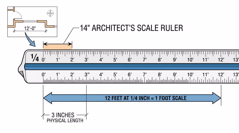
Using an architect’s scale:
An architect’s scale has multiple scales printed on its edges. The most common for residential drawings is 1/4" = 1’-0", which means every 1/4 inch on your drawing represents 1 foot in real life. To draw a 12-foot wall, you would measure 3 inches on your paper using the 1/4-inch scale edge.
Option B: Mechanical Drawing
A mechanical drawing shows a physical object — a tool, a device, a bracket, a toy — with enough detail that someone could manufacture it. The two main styles are:
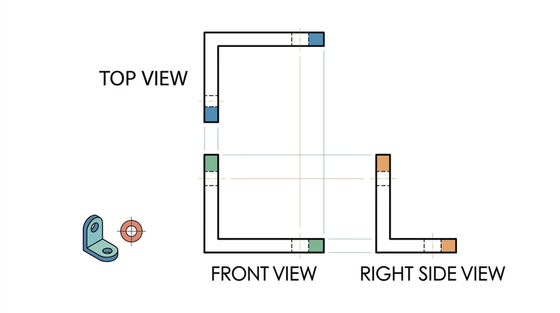
Orthographic (Third-Angle) Projection — Shows the object from three views: front, top, and right side. Each view shows the object as if you are looking straight at it from that direction. This is the standard for manufacturing drawings in the United States.
Isometric Drawing — Shows the object in a 3D-looking view where all three axes (width, height, depth) are drawn at equal angles (30 degrees from horizontal). Isometric drawings give a good visual sense of the object’s shape but are not used for dimensioning in manufacturing.
Good project ideas:
- A simple hand tool (hammer, wrench, screwdriver)
- A bookend, phone stand, or shelf bracket
- A game piece or puzzle
- A birdhouse or toolbox
Key elements to include:
- At least two orthographic views (front and top, or front and side) OR one isometric view
- Dimensions with proper dimension lines, extension lines, and arrowheads
- Notes on materials and manufacturing methods
- A bill of materials for at least three components or raw materials
- A section view if the object has interior features that are not visible from the outside
Option C: Electrical Schematic
An electrical schematic is a diagram that shows how electronic components connect to form a circuit. Unlike architectural and mechanical drawings, schematics are usually not drawn to scale — the layout is arranged for clarity, not to represent physical positions.
Standard symbols you will use:
| Component | Symbol Description |
|---|---|
| Resistor | Zigzag line |
| Capacitor | Two parallel lines with a gap |
| Inductor | Series of loops |
| Diode | Triangle pointing at a line |
| Transistor | Circle with three leads (base, collector, emitter) |
| Battery | Alternating long and short parallel lines |
| Ground | Three horizontal lines decreasing in length |
| Switch | Break in the line with a hinged connector |
Good project ideas:
- A simple AM radio circuit
- An LED flashlight circuit with resistor and switch
- A basic amplifier circuit
- A 555 timer circuit (used in thousands of electronics projects)
Key elements to include:
- All components drawn with standard IEEE/ANSI symbols
- Component labels (R1, R2, C1, etc.)
- Component values (10kΩ, 100μF, etc.)
- Connection dots at wire junctions
- Power supply connections (V+ and ground)
- A bill of materials listing all major components with their values and quantities
Which Option Should You Choose?
| Option | Best For | You Will Need |
|---|---|---|
| A — Architectural | Scouts interested in buildings, construction, interior design | Architect’s scale, tape measure for measuring real rooms |
| B — Mechanical | Scouts interested in machines, manufacturing, 3D objects | Engineer’s scale, an interesting object to draw |
| C — Electrical | Scouts interested in electronics, circuits, radio, robotics | Reference for standard symbols, a circuit to draw |
Talk with your counselor about which option fits your interests. Whichever you choose, your manual drawing for Requirement 2 should be on the formatted sheet you prepared in Requirement 1, with all title block information filled in.
In Requirement 3, you will create a similar drawing — but this time using CAD software instead of pencil and paper. Completing both gives you a direct comparison of manual and digital drafting.