Electronics Merit Badge — Complete Digital Resource Guide
https://merit-badge.university/merit-badges/electronics/guide/
Introduction & Overview
Every time you unlock your phone, flip a light switch, or hear music through a speaker, electronics are at work. The circuits inside those devices — tiny pathways of copper, silicon, and solder — carry electrical signals that make modern life possible. Understanding how those circuits work gives you something most people never have: the ability to build, fix, and invent things that run on electricity.
The Electronics merit badge takes you from reading schematic diagrams all the way to building a working circuit with your own hands. Along the way, you will learn to solder, measure voltage and current, decode resistor color bands, and think in binary — the language that every computer on the planet speaks.

Then and Now
Then — The story of electronics begins in the early 1900s, when inventors discovered that a vacuum tube — a sealed glass bulb with metal elements inside — could amplify weak radio signals and switch electrical currents on and off. Vacuum tubes powered the first radios, televisions, and computers. ENIAC, the first general-purpose electronic computer built in 1945, used over 17,000 vacuum tubes and filled an entire room. Those tubes burned hot, failed constantly, and consumed enormous amounts of power.
Now — In 1947, three physicists at Bell Labs — John Bardeen, Walter Brattain, and William Shockley — invented the transistor, a tiny semiconductor device that could do everything a vacuum tube did but was smaller, cooler, cheaper, and far more reliable. That invention changed the world. Today, a single microprocessor chip the size of your thumbnail contains billions of transistors. Your smartphone has more computing power than all the computers NASA used to put astronauts on the moon combined. Electronics now touch every part of daily life — from medical devices that save lives to satellites that guide your GPS.
Get Ready
This badge combines hands-on building with real science. You will solder components, read schematics, crunch numbers with Ohm’s law, and convert between decimal and binary. None of it is as hard as it sounds — and by the end, you will have a working circuit you built yourself to prove it.
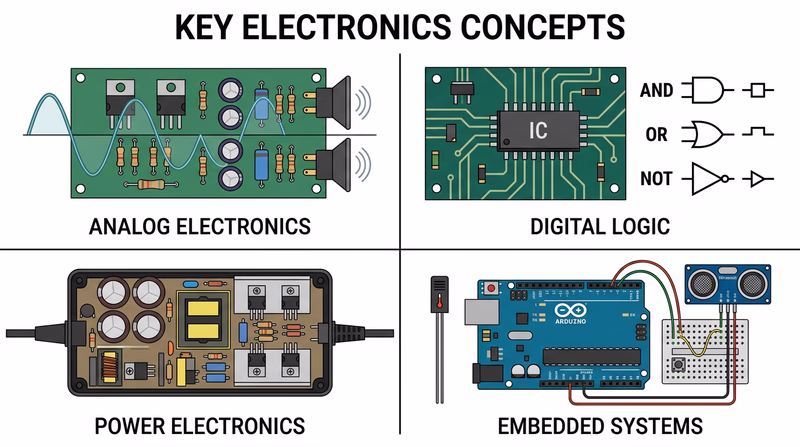
Kinds of Electronics
Electronics is a broad field. Here are the major branches you will encounter in this badge and beyond.
Analog Electronics
Analog circuits work with signals that change smoothly and continuously — like the wave of sound from a guitar string or the gradual dimming of a light. Amplifiers, radios, and audio equipment are classic analog devices. When you turn a volume knob and hear the sound get gradually louder, that is analog electronics at work.
Digital Electronics
Digital circuits deal in only two states: on and off, represented by the numbers 1 and 0. Every computer, smartphone, and digital watch runs on digital logic. By combining millions of simple on/off switches (transistors), digital circuits can perform incredibly complex calculations.
Power Electronics
Power electronics control and convert electrical energy — changing AC wall power to DC for your laptop charger, regulating voltage for sensitive components, or managing the power flow in an electric vehicle. Without power electronics, most of your devices would burn out the moment you plugged them in.
Embedded Systems
An embedded system is a small computer built into a larger device to perform a specific job. The controller in your microwave, the sensor system in a car’s anti-lock brakes, and the chip inside a fitness tracker are all embedded systems. Arduino and Raspberry Pi boards have made embedded systems accessible to hobbyists and Scouts alike.
Req 1 — Safety Precautions
A short circuit can destroy a component in a fraction of a second. A soldering iron tip reaches over 600 degrees Fahrenheit. A capacitor can hold a dangerous charge long after a device has been unplugged. Electronics work is rewarding, but it demands respect for the real hazards involved. Understanding these precautions is not just a requirement — it is the foundation that makes everything else in this badge possible.
Electrical Hazards
Shock and Electrocution
Electric shock occurs when current flows through your body. The severity depends on the amount of current, the path it takes, and how long the exposure lasts. As little as 10 milliamps (0.01 amps) can cause painful muscle contractions. At 100 milliamps, the current can stop your heart.
- Never work on a live circuit. Always unplug devices or disconnect power before opening them up.
- Capacitors store charge. Large capacitors in televisions, monitors, and power supplies can hold a lethal charge for hours or even days after the device is unplugged. Never touch capacitor leads without properly discharging them first.
- Use one hand when possible. If current enters one hand and exits the other, it passes through your heart. Working with one hand behind your back (or in your pocket) is an old electrician’s trick that reduces this risk.
- Keep your work area dry. Water conducts electricity. Wet hands, damp floors, or spilled drinks near your workbench create a direct path for current to flow through your body.
Burns
Soldering irons operate between 600 and 800 degrees Fahrenheit. Burns are one of the most common injuries in electronics work.
- Always return the iron to its stand when you are not actively soldering.
- Never touch the tip or the metal barrel of a hot iron.
- Let solder joints cool before touching them — freshly soldered connections can cause blistering burns.
- Wear safety glasses. Solder can occasionally spit or splatter.
Fumes and Ventilation
When solder melts, the flux core releases fumes that can irritate your eyes, nose, and lungs. Lead-based solder (still used in many hobby applications) also releases small amounts of lead vapor.
- Work in a ventilated area. Open a window, use a fan to push fumes away from your face, or use a fume extractor.
- Wash your hands after handling solder, especially lead-based solder. Never eat or drink at your electronics workbench.
- Consider lead-free solder — it is slightly harder to work with, but it eliminates lead exposure.
Component Protection
Electronics safety is not just about protecting yourself — it is also about protecting the components you are working with.
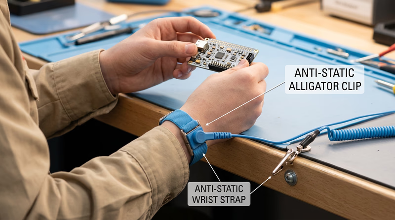
Electrostatic Discharge (ESD)
Static electricity that you barely feel — the kind that shocks you when you touch a doorknob — carries thousands of volts. That tiny spark can permanently destroy sensitive components like integrated circuits and transistors.
- Use an anti-static wrist strap connected to a grounded surface when handling sensitive components.
- Touch a grounded metal object before reaching into a bag of components.
- Store sensitive parts in anti-static bags (the gray or pink bags components come in).
- Avoid working on carpet — shuffling your feet on carpet generates significant static charge.
Heat Damage
Excessive heat from a soldering iron can destroy components before you even finish assembling your circuit. You will learn specific techniques for preventing heat damage in Req 3b, but the general rule is simple: get the solder joint done quickly and move on.
Polarity and Voltage
Many components are polarized — they must be installed in the correct direction. Inserting an LED, electrolytic capacitor, or diode backwards can destroy it instantly or cause it to fail later.
- Check polarity markings before inserting components. Look for flat edges on LEDs, stripe markings on diodes, and plus/minus markings on capacitors.
- Double-check voltage ratings. Applying too much voltage to a component rated for a lower value will damage or destroy it.
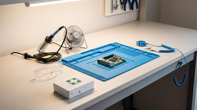
Workspace Safety
Safe Electronics Workspace
Set up your workbench for safe, productive work- Well-lit work surface: Good lighting prevents mistakes and eye strain.
- Ventilation: A small fan or fume extractor positioned to carry fumes away from your face.
- Heat-resistant surface: A silicone soldering mat or ceramic tile protects your table.
- Organized tools: Each tool has a designated spot so you never reach blindly.
- Clear of clutter: Stray wires, loose components, and drinks do not belong near active circuits.
- Fire extinguisher nearby: A Class C extinguisher (rated for electrical fires) should be within reach.
- First-aid kit: Burns are the most common electronics injury — have burn gel and bandages ready.
Req 2 — Reading & Drawing Schematics
This requirement covers two related tasks:
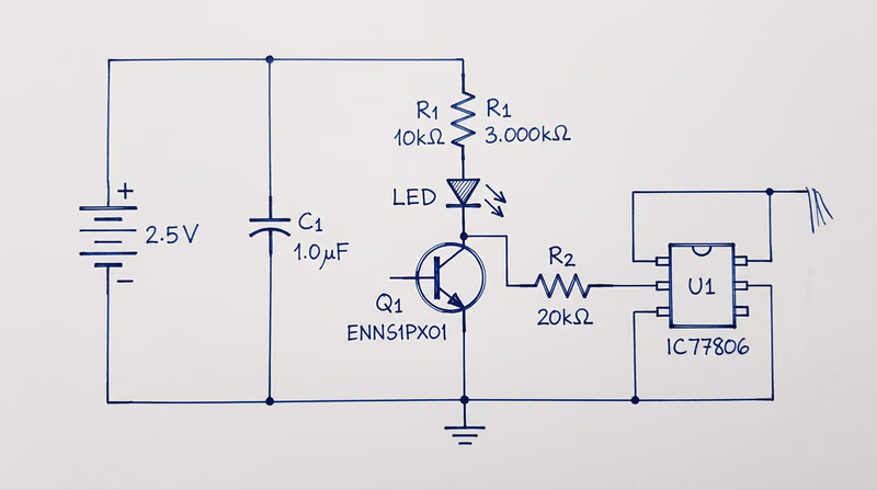
- Req 2a — Draw a simple schematic diagram with resistors, capacitors, and transistors or integrated circuits, using correct symbols and labels.
- Req 2b — Explain the purpose of each part in your schematic.
What Is a Schematic Diagram?
A schematic diagram is the blueprint of an electronic circuit. Instead of showing what a circuit physically looks like, it uses standardized symbols to show how components are connected electrically. Every engineer, technician, and hobbyist in the world reads the same symbols — a schematic drawn in Tokyo can be understood in Texas without translation.
Think of a schematic the way you think of a road map. A road map does not show every tree and building — it shows the routes and intersections you need to navigate. A schematic does the same thing for electrical pathways.
Essential Component Symbols
Before you can draw a schematic, you need to know the symbols. Here are the components you will use:
Resistors
Symbol: A zigzag line (US standard) or a rectangle (international standard).
Purpose: A resistor limits the flow of electrical current. It is like a narrow section of a water pipe — it slows things down. Resistors protect components from receiving too much current and divide voltage within a circuit. Resistance is measured in ohms (the symbol looks like the Greek letter omega). You will learn much more about resistors and how to read their color-coded values in Req 5c.
Capacitors
Symbol: Two parallel lines (for non-polarized) or one straight line and one curved line (for polarized/electrolytic).
Purpose: A capacitor stores electrical energy temporarily, like a tiny rechargeable battery that charges and discharges very quickly. Capacitors smooth out voltage fluctuations, filter signals, and provide bursts of energy when needed. Capacitance is measured in farads, though most capacitors you will work with are measured in microfarads (uF) or picofarads (pF).
Transistors
Symbol: A circle with three leads labeled Base (B), Collector (C), and Emitter (E). An arrow on the emitter indicates current direction (pointing outward for NPN, inward for PNP).
Purpose: A transistor is the fundamental building block of modern electronics. It works as both a switch (turning current on and off) and an amplifier (making weak signals stronger). A small current at the base controls a much larger current flowing between the collector and emitter. Billions of transistors working together inside a microprocessor make computing possible.
Integrated Circuits (ICs)
Symbol: A rectangle with numbered pins along the sides.
Purpose: An integrated circuit is a miniature circuit — sometimes containing millions of components — manufactured on a single chip of silicon. Instead of wiring up hundreds of individual transistors and resistors, you can use one IC that does the same job. Common ICs include the 555 timer (used in countless hobby projects), operational amplifiers, and microcontrollers.
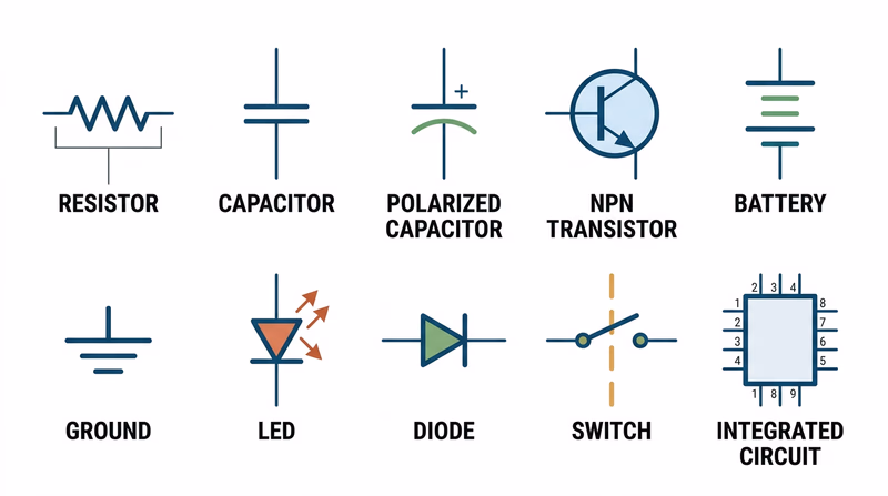
Additional Symbols You Should Know
Your schematic will also need these basic symbols:
- Battery/Power Source — Long and short parallel lines (long = positive, short = negative).
- Ground — Three horizontal lines of decreasing length, or a downward-pointing triangle. Ground is the reference point for all voltages in a circuit.
- Wires — Straight lines connecting components. A dot at an intersection means the wires are connected; a small arc or bridge means they cross without connecting.
- Switch — An open gap in a line with a movable contact.
How to Draw a Schematic
Schematic Drawing Steps
Follow these steps to create a clean, readable schematic- Start with the power source: Place the battery or power supply at the top left, with positive voltage at the top and ground at the bottom.
- Draw current flow left to right: Arrange components so the signal or current flows from left to right across the page, like reading a sentence.
- Use straight lines: Connect components with horizontal and vertical lines only — no diagonal wires.
- Label every component: Use standard designators — R1, R2 for resistors, C1, C2 for capacitors, Q1, Q2 for transistors, U1, U2 for ICs.
- Add values: Write the value next to each component — 470 ohm, 10uF, 2N2222 (a common transistor part number).
- Mark polarity: Show the positive and negative leads of polarized components (electrolytic capacitors, LEDs, diodes).
- Keep it neat: A good schematic is easy to read. Spacing, alignment, and clear labeling matter.
Explaining Your Circuit (Req 2b)
After you draw your schematic, you need to explain what each part does. Do not just name the components — describe their role in your specific circuit. For example:
- “R1 (470 ohm resistor) limits the current flowing through the LED so it does not burn out.”
- “C1 (10uF capacitor) smooths out voltage ripples from the power supply.”
- “Q1 (NPN transistor) acts as a switch — when the sensor sends a signal to the base, Q1 turns on and allows current to flow through the motor.”
The key is connecting the general purpose of each component to its specific job in the circuit you drew.
Req 3 — Soldering Techniques
This requirement covers three soldering skills you need to demonstrate:
- Req 3a — Show the right way to solder and desolder.
- Req 3b — Show how to avoid heat damage to electronic components.
- Req 3c — Explain the function of a printed circuit board and the precautions for soldering on one.
Soldering is where electronics stops being theory and becomes hands-on craft. A good solder joint creates a reliable electrical and mechanical connection that can last for decades. A bad one can cause intermittent failures that are maddening to troubleshoot. The difference comes down to technique, and technique is something you can master with practice.
Req 3a — How to Solder
What Is Soldering?
Soldering joins two metal surfaces by melting a filler metal (solder) between them. The solder — a metal alloy with a relatively low melting point — flows into the joint by capillary action and solidifies to form a strong electrical connection. Unlike welding, soldering does not melt the parts being joined.
Solder comes as a thin wire on a spool. Most hobby solder has a rosin flux core — a chemical that cleans the metal surfaces as the solder melts, allowing it to flow and bond properly.
Step-by-Step Soldering
- Prepare your iron. Turn on your soldering iron and let it heat up fully (usually 2-3 minutes). The tip should be clean and shiny.
- Tin the tip. Touch a small amount of solder to the hot tip so it is coated with a thin layer of shiny solder. This improves heat transfer. Wipe excess on a damp sponge or brass tip cleaner.
- Position the components. Insert the component leads through the circuit board holes (or position them for a wire-to-wire joint). The parts should be stable and not move during soldering.
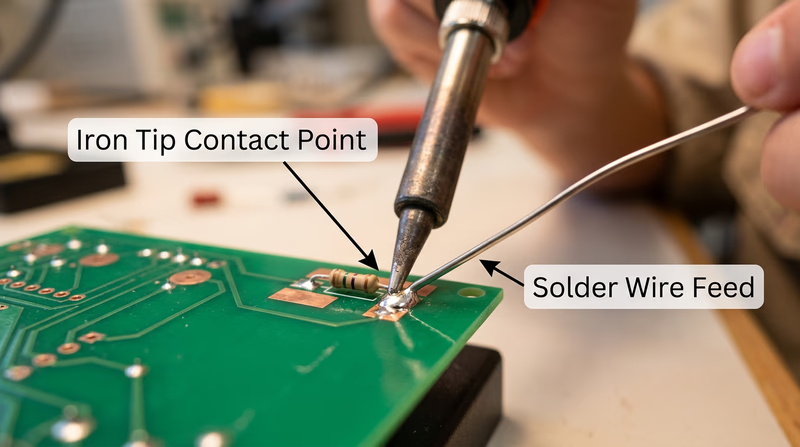
- Heat the joint, not the solder. Place the iron tip so it touches both the component lead AND the copper pad on the board simultaneously. Hold it there for 2-3 seconds to heat the joint.
- Feed solder into the joint. While the iron is still in contact, touch the solder wire to the joint (not to the iron tip). The solder should melt and flow smoothly around the lead and pad, pulled in by capillary action.
- Remove the solder, then the iron. Pull the solder wire away first, then lift the iron away. The entire process should take 3-5 seconds.
- Inspect the joint. A good solder joint looks like a small, shiny, cone-shaped mound that fully wets both the lead and the pad. It should not be a dull blob sitting on top of the pad.
Good Joints vs. Bad Joints
| Joint Type | Appearance | Cause | Fix |
|---|---|---|---|
| Good joint | Shiny, cone-shaped, smooth | Proper technique | None needed |
| Cold joint | Dull, grainy, rough surface | Joint not hot enough, or solder applied to iron instead of joint | Reheat and add flux |
| Excess solder | Large blob, may bridge to adjacent pads | Too much solder applied | Use solder wick to remove excess |
| Insufficient solder | Thin, does not fully coat the pad | Not enough solder or poor wetting | Reheat and add more solder |
| Solder bridge | Solder connects two adjacent pads that should be separate | Excess solder or pads too close | Use solder wick or desoldering pump |
How to Desolder
Mistakes happen — that is why desoldering is an essential skill. Two common tools make it possible:
Solder wick (desoldering braid) — A flat copper braid that absorbs molten solder. Place the braid over the joint, press your hot iron on top of the braid, and watch the solder wick up into the copper. Trim off the used section and repeat if needed.
Desoldering pump (solder sucker) — A spring-loaded vacuum tool. Press the plunger down to cock it, heat the solder joint until it melts, then position the pump nozzle right next to the molten solder and release the plunger. The sudden vacuum sucks the molten solder away.
Req 3b — Preventing Heat Damage
Electronic components are sensitive to heat. A transistor, IC, or LED can be permanently damaged if exposed to too much heat during soldering. Here is how to protect them:
Time Is Everything
The single most important rule: solder quickly. A good joint should take 3-5 seconds. If you are holding the iron on a joint for 10 or more seconds, something is wrong — usually the joint is not clean, or the iron is not hot enough.
Use a Heat Sink
A heat sink is a clip (often an alligator clip) that you attach to the component lead between the component body and the solder joint. The clip absorbs heat traveling up the lead, preventing it from reaching the component. This is especially important for heat-sensitive parts like transistors, diodes, and ICs.
Temperature Control
If your soldering iron has adjustable temperature, set it appropriately:
- Lead-based solder: 600-650 degrees Fahrenheit (315-345 degrees Celsius)
- Lead-free solder: 650-750 degrees Fahrenheit (345-400 degrees Celsius)
A hotter iron is not necessarily better. Higher temperatures increase the risk of heat damage and can burn the flux before it does its job.
Req 3c — Printed Circuit Boards
What Is a PCB?
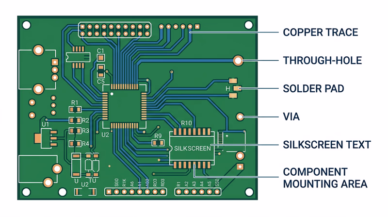
A printed circuit board (PCB) is a flat board made of fiberglass or similar insulating material with thin copper pathways — called traces — printed (etched) onto its surface. These traces replace the tangle of individual wires that would otherwise be needed to connect components. The board provides both the electrical connections and the physical structure to hold everything in place.
Modern PCBs can have multiple layers of traces sandwiched inside the board, with tiny holes called vias connecting traces on different layers. Your smartphone’s motherboard has dozens of layers packed into a board thinner than a credit card.
PCB Soldering Precautions
Soldering on a PCB requires extra care because the copper traces are thin and delicate:
- Do not overheat pads. Excessive heat can cause the copper pad to delaminate — literally peel off the board. Once a pad lifts, the board is damaged and may be unrepairable.
- Do not apply pressure. Let the solder flow naturally. Pushing the iron hard against the board can crack traces or damage the fiberglass substrate.
- Watch for solder bridges. PCB traces are close together. Excess solder can bridge across two adjacent pads or traces, creating a short circuit. Inspect your work carefully with a magnifying glass.
- Follow the silkscreen. The white printed markings on a PCB (called the silkscreen) show you where each component goes, its orientation, and its reference designator (R1, C1, Q1, etc.). Always match the component to its silkscreen marking.
- Solder in order of height. Start with the shortest components (resistors, diodes) and work up to the tallest (capacitors, connectors). This keeps components from falling out when you flip the board over to solder.
Req 4a — Control, Logic & Analog
This requirement asks you to understand and discuss three topics:
- 4a1 — How to use electronics for a control purpose.
- 4a2 — The basic principles of digital logic.
- 4a3 — How to use electronics for three different analog applications.
These three topics represent the major ways electronic circuits interact with the real world. Control circuits make decisions and take action. Digital logic processes information in the language of ones and zeros. Analog circuits handle the continuously varying signals that come from the physical world around us.
4a1 — Electronics for Control
A control circuit uses electronic components to monitor a condition and respond automatically. Instead of a person flipping a switch, the circuit itself decides when to act.
The Control Loop
Every electronic control system follows the same basic pattern:
- Sense — A sensor measures something in the environment (temperature, light, motion, moisture).
- Decide — A controller (which could be as simple as a single transistor or as complex as a microprocessor) compares the sensor reading to a target value.
- Act — An output device (motor, heater, buzzer, LED, relay) responds based on the controller’s decision.
Real-World Examples
Thermostat — A temperature sensor reads the room temperature. If it drops below your set point, the controller activates the furnace. When the temperature reaches the target, the controller shuts the furnace off. This is a classic feedback loop — the output (heat) changes the input (temperature), which changes the output, and so on.
Motion-activated light — A passive infrared (PIR) sensor detects body heat moving through its field of view. The sensor sends a signal to a transistor or relay that switches on the light. After a set time with no motion detected, the circuit turns the light off.
Automatic irrigation system — A moisture sensor in the soil measures how dry the ground is. When moisture drops below a threshold, a microcontroller opens a solenoid valve to water the plants. When the soil is moist enough, the valve closes.
Try It Yourself
For your counselor discussion, think of a control application you have seen or used. Describe the sensor, the controller, and the output device. Can you identify the feedback loop?
4a2 — Basic Principles of Digital Logic
Digital electronics operate on a simple idea: everything is either on or off, represented by the numbers 1 and 0. These two states are called binary — and from just these two values, digital circuits can perform any computation, store any data, and control any process.
Logic Gates — The Building Blocks
Digital circuits are built from logic gates — tiny circuits that take one or two binary inputs and produce one binary output based on simple rules. There are a few fundamental gates:
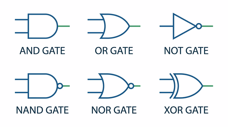
AND gate — Output is 1 only when ALL inputs are 1. Think of it as two switches in series: both must be closed for current to flow.
| Input A | Input B | Output |
|---|---|---|
| 0 | 0 | 0 |
| 0 | 1 | 0 |
| 1 | 0 | 0 |
| 1 | 1 | 1 |
OR gate — Output is 1 when ANY input is 1. Think of two switches in parallel: either one lets current through.
| Input A | Input B | Output |
|---|---|---|
| 0 | 0 | 0 |
| 0 | 1 | 1 |
| 1 | 0 | 1 |
| 1 | 1 | 1 |
NOT gate (Inverter) — Flips the input. 1 becomes 0, and 0 becomes 1. It has only one input.
| Input | Output |
|---|---|
| 0 | 1 |
| 1 | 0 |
Combining Gates
By combining these three basic gates, engineers build everything from simple alarm circuits to entire processors. A NAND gate (NOT + AND) and a NOR gate (NOT + OR) are especially important because each one alone can be used to build any other type of gate — making them “universal gates.”
From Gates to Computers
A processor is nothing more than billions of logic gates connected in carefully designed patterns. An adder circuit — which adds two binary numbers — can be built from just AND, OR, and XOR gates. Stack enough adders together, add some memory (which is made from gates too), and you have the core of a computer.
4a3 — Analog Applications
While digital circuits deal in 1s and 0s, analog circuits handle signals that vary continuously — like sound waves, temperature readings, and light intensity. The physical world is analog, and analog electronics are how we interface with it.
Three Analog Applications to Discuss
Here are several analog applications you can choose from when speaking with your counselor. Pick three that interest you and be ready to explain how each one works.
Audio amplification — A microphone converts sound waves into a tiny electrical signal. An amplifier circuit boosts that weak signal strong enough to drive a speaker. The amplified signal is a faithful copy of the original sound wave — just larger. Guitar amps, PA systems, and hearing aids all use this principle.
Radio transmission and reception — A radio transmitter creates a high-frequency carrier wave and modulates (varies) it to carry audio information. AM radio varies the amplitude (height) of the wave. FM radio varies the frequency (speed) of the wave. A receiver picks up the signal with an antenna, separates the audio from the carrier, and sends it to a speaker.
Sensor measurement — A thermistor (temperature-sensitive resistor) changes its resistance as temperature changes. An analog circuit converts that resistance change into a proportional voltage, which can be read by a meter or displayed on a gauge. Medical thermometers, weather stations, and automotive coolant gauges use this approach.
Voltage regulation — A voltage regulator takes an unsteady input voltage and produces a stable, constant output voltage. Your phone charger takes 120V AC from the wall and converts it to a steady 5V DC that your phone needs. Without regulation, voltage fluctuations would damage sensitive components.
Light dimming — A dimmer switch uses an analog circuit (typically a triac or potentiometer) to control how much power reaches a light bulb. Turning the knob smoothly varies the brightness from full on to completely off — a continuous range, not just on/off.
All About Circuits — Tutorials Free, comprehensive online textbook covering analog and digital electronics from fundamentals to advanced topics. Link: All About Circuits — Tutorials — https://www.allaboutcircuits.com/textbook/Req 4b — Binary & Decimal Conversion
In Req 4a, you learned that digital electronics speak in binary — a number system with only two digits: 0 and 1. Now you need to become fluent in translating between the decimal system (the base-10 system you use every day) and binary (the base-2 system that every computer uses internally).
Why Binary Matters
Computers use binary because transistors — the tiny switches inside every chip — have two states: on (1) and off (0). A single binary digit is called a bit. Eight bits grouped together form a byte, which can represent any number from 0 to 255. Every number, letter, color, and sound in a computer is ultimately stored as a pattern of bits.
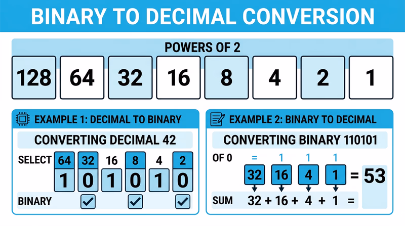
Understanding Place Values
The key to conversion is understanding place values. In the decimal system, each position is worth 10 times more than the one to its right:
| Position | Thousands | Hundreds | Tens | Ones |
|---|---|---|---|---|
| Place value | 1000 | 100 | 10 | 1 |
| Power of 10 | 10^3 | 10^2 | 10^1 | 10^0 |
Binary works the same way, but each position is worth 2 times more than the one to its right:
| Position | 128s | 64s | 32s | 16s | 8s | 4s | 2s | 1s |
|---|---|---|---|---|---|---|---|---|
| Place value | 128 | 64 | 32 | 16 | 8 | 4 | 2 | 1 |
| Power of 2 | 2^7 | 2^6 | 2^5 | 2^4 | 2^3 | 2^2 | 2^1 | 2^0 |
Decimal to Binary — The Division Method
To convert a decimal number to binary, repeatedly divide by 2 and record the remainders. Read the remainders from bottom to top.
Example: Convert 42 to binary
| Step | Division | Quotient | Remainder |
|---|---|---|---|
| 1 | 42 / 2 | 21 | 0 |
| 2 | 21 / 2 | 10 | 1 |
| 3 | 10 / 2 | 5 | 0 |
| 4 | 5 / 2 | 2 | 1 |
| 5 | 2 / 2 | 1 | 0 |
| 6 | 1 / 2 | 0 | 1 |
Reading the remainders from bottom to top: 42 in decimal = 101010 in binary.
Example: Convert 13 to binary
| Step | Division | Quotient | Remainder |
|---|---|---|---|
| 1 | 13 / 2 | 6 | 1 |
| 2 | 6 / 2 | 3 | 0 |
| 3 | 3 / 2 | 1 | 1 |
| 4 | 1 / 2 | 0 | 1 |
Reading bottom to top: 13 = 1101
Example: Convert 200 to binary
| Step | Division | Quotient | Remainder |
|---|---|---|---|
| 1 | 200 / 2 | 100 | 0 |
| 2 | 100 / 2 | 50 | 0 |
| 3 | 50 / 2 | 25 | 0 |
| 4 | 25 / 2 | 12 | 1 |
| 5 | 12 / 2 | 6 | 0 |
| 6 | 6 / 2 | 3 | 0 |
| 7 | 3 / 2 | 1 | 1 |
| 8 | 1 / 2 | 0 | 1 |
Reading bottom to top: 200 = 11001000
Binary to Decimal — The Addition Method
To convert binary to decimal, write out the place values above each bit, then add up the place values wherever you see a 1.
Example: Convert 110101 to decimal
| Place value | 32 | 16 | 8 | 4 | 2 | 1 |
|---|---|---|---|---|---|---|
| Binary digit | 1 | 1 | 0 | 1 | 0 | 1 |
Add the place values where the digit is 1: 32 + 16 + 4 + 1 = 53
Example: Convert 10010 to decimal
| Place value | 16 | 8 | 4 | 2 | 1 |
|---|---|---|---|---|---|
| Binary digit | 1 | 0 | 0 | 1 | 0 |
Add: 16 + 2 = 18
Example: Convert 11111111 to decimal
| Place value | 128 | 64 | 32 | 16 | 8 | 4 | 2 | 1 |
|---|---|---|---|---|---|---|---|---|
| Binary digit | 1 | 1 | 1 | 1 | 1 | 1 | 1 | 1 |
Add: 128 + 64 + 32 + 16 + 8 + 4 + 2 + 1 = 255
Quick Check — Place Value Method for Decimal to Binary
There is a faster method that some people prefer. Start with the largest power of 2 that fits into your number, subtract it, and continue:
Convert 45 to binary:
- 45 >= 32? Yes. Write 1. Remainder: 45 - 32 = 13
- 13 >= 16? No. Write 0.
- 13 >= 8? Yes. Write 1. Remainder: 13 - 8 = 5
- 5 >= 4? Yes. Write 1. Remainder: 5 - 4 = 1
- 1 >= 2? No. Write 0.
- 1 >= 1? Yes. Write 1. Remainder: 0
Result: 45 = 101101
Req 4c — Build a Circuit Project
This is where everything comes together. You will choose one of three project types, find or create a schematic, build the circuit, and explain how it works. The three options are:
- A control device
- A digital circuit
- An analog circuit
Each option connects directly to the concepts you studied in Req 4a. Pick the one that interests you most — there is no advantage to choosing one over another.
Option 1: A Control Device
A control device senses a condition and responds automatically. Here are some beginner-friendly control projects:
Light-activated night light — Uses a photoresistor (light-dependent resistor) and a transistor to turn on an LED when the room gets dark. When light hits the photoresistor, its resistance drops and keeps the transistor off. In the dark, resistance rises, the transistor turns on, and the LED lights up.
Temperature-triggered fan — Uses a thermistor and a transistor to switch on a small DC fan when the temperature rises above a threshold. This is the same principle behind the cooling fan in your computer.
Moisture alarm — Two probes in the soil connect to a simple transistor circuit. When the soil is dry (high resistance), the circuit stays quiet. When water bridges the probes (low resistance), a buzzer sounds.
Option 2: A Digital Circuit
A digital circuit processes binary signals (1s and 0s) using logic gates. Beginner-friendly digital projects include:
LED binary counter — Uses a 555 timer IC to generate clock pulses and a 4017 decade counter IC to light LEDs in sequence. This demonstrates how digital circuits count in a predictable, repeating pattern.
Logic gate demonstrator — Wire up AND, OR, and NOT gates using a basic logic IC (like the 7408 AND gate chip). Use switches for inputs and LEDs for outputs. You can physically see how different input combinations produce different outputs — exactly like the truth tables you studied in Req 4a.
555 timer blinker — The venerable 555 timer IC configured in astable mode generates a continuous square wave that blinks an LED on and off at a rate you control by choosing different resistor and capacitor values.
Option 3: An Analog Circuit
An analog circuit processes continuously varying signals. Good beginner analog projects include:
Audio amplifier — Uses an LM386 audio amplifier IC to boost a weak audio signal (from a phone or MP3 player) strong enough to drive a small speaker. You will hear the difference between the original quiet signal and the amplified output.
AM radio receiver — A simple crystal radio or single-transistor radio picks up AM broadcast signals using an antenna, a coil, a capacitor, and a diode. No batteries required for the simplest version — the radio signal itself provides the power.
LED brightness controller — A potentiometer (variable resistor) connected to a transistor controls LED brightness smoothly from off to full brightness. This demonstrates analog control of power.
Planning Your Project
Regardless of which option you choose, follow this process:
Circuit Project Checklist
Steps to complete your Req 4c project- Choose your project type: Control device, digital circuit, or analog circuit.
- Find a schematic: Search online, use a book, or ask your counselor. Reliable sources include Instructables, Adafruit, SparkFun, and electronics textbook websites.
- Gather your components: Make a bill of materials listing every component and its value. Verify you have everything before starting.
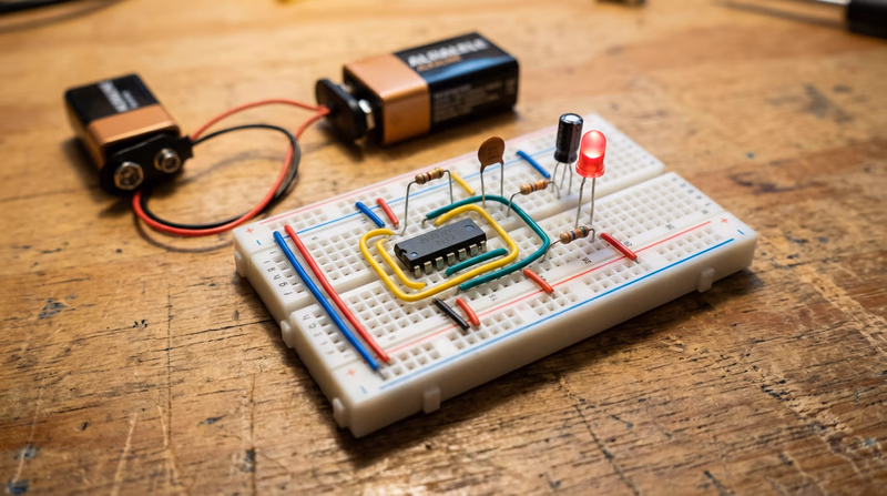
- Build on a breadboard first: A breadboard lets you test your circuit without soldering. If it does not work, you can rearrange components easily.
- Test the circuit: Does it do what the schematic says it should? If not, troubleshoot. Check your wiring against the schematic, verify component values, and look for loose connections.
- Transfer to a permanent board (optional): Once it works on the breadboard, you can solder it onto a perfboard for a more permanent build.
- Prepare your explanation: Walk through the schematic and explain what each component does and how the circuit operates as a system.
Explaining Your Circuit
When you meet with your counselor, be ready to:
- Show your schematic and identify each component by its symbol and reference designator.
- Trace the signal path — follow the current from the power source through each component and explain what happens at each stage.
- Describe the purpose of each major component — not just “this is a resistor,” but “R1 limits the current to the LED so it does not exceed its 20mA rating.”
- Demonstrate that it works — power it up and show the output.
- Explain what would happen if you changed a component — for example, “if I used a larger capacitor, the blink rate would slow down.”
Req 5a — Ohm's Law
If electronics has one law you absolutely must know, this is it. Ohm’s law describes the relationship between voltage, current, and resistance in every electrical circuit. Once you understand it, you can predict how a circuit will behave, calculate the right component values, and troubleshoot problems logically instead of guessing.
The Three Variables
Before diving into the math, make sure you understand what each variable means:
Voltage (V) — The electrical “pressure” that pushes current through a circuit. Measured in volts. Think of it as the height of a waterfall — the higher the falls, the more force the water has.
Current (I) — The flow of electrical charge through a circuit. Measured in amperes (amps). Think of it as the amount of water flowing over the waterfall — gallons per second.
Resistance (R) — The opposition to current flow. Measured in ohms (the Greek letter omega). Think of it as a narrow pipe that restricts water flow — the narrower the pipe, the less water gets through.
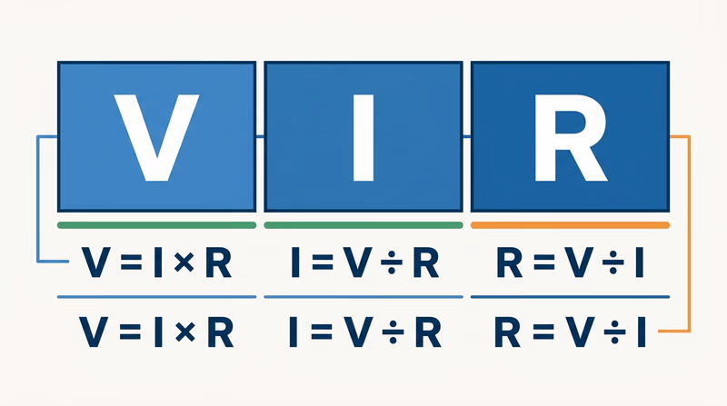
The Formula
Ohm’s law is expressed in three equivalent forms:
- V = I x R (Voltage equals Current times Resistance)
- I = V / R (Current equals Voltage divided by Resistance)
- R = V / I (Resistance equals Voltage divided by Current)
All three say the same thing — they are just rearranged depending on which variable you need to find. Cover up the variable you are solving for, and the remaining two tell you what to do.
Solving Problems
Example 1: Find the Current
A 9V battery powers a circuit with 450 ohms of resistance. How much current flows?
Given: V = 9V, R = 450 ohms Find: I
I = V / R = 9 / 450 = 0.02 amps = 20 milliamps (mA)
Example 2: Find the Resistance
You want to limit current through an LED to 20mA using a 5V power supply. What resistor do you need?
Given: V = 5V, I = 20mA = 0.02A Find: R
R = V / I = 5 / 0.02 = 250 ohms
(In practice, you would use the nearest standard resistor value: 270 ohms.)
Example 3: Find the Voltage
A circuit has a 1,000-ohm resistor with 5mA of current flowing through it. What is the voltage across the resistor?
Given: R = 1,000 ohms, I = 5mA = 0.005A Find: V
V = I x R = 0.005 x 1,000 = 5 volts
Why It Matters
Ohm’s law is not just an equation for a test — it is a tool you will use every time you design or troubleshoot a circuit. When you calculated the resistor for the LED example above, you did exactly what a working engineer does. Without that calculation, you would either burn out the LED (too much current) or get a dim, barely visible light (too little current).
In your circuit project, Ohm’s law determined the value of every resistor in the schematic. And when you use a multimeter to measure voltage and current in a circuit, you are verifying that Ohm’s law holds true.
Practice Problems
Try these on your own before your counselor meeting. Work through the formula and check your answers:
- A 12V battery powers a 600-ohm circuit. What is the current?
- You need 50mA through a circuit powered by 3.3V. What resistance do you need?
- A 2,200-ohm resistor carries 10mA of current. What voltage is across it?
Req 5b — Test Equipment
You can look at a circuit board all day and never know whether it is working correctly. Electricity is invisible. You cannot see voltage, feel current (safely), or hear resistance. Test equipment gives you eyes into the invisible world of electrical signals — and without it, troubleshooting a broken circuit is nothing more than guesswork.
Why Test Equipment Matters
Every time you build, repair, or debug a circuit, you need to answer questions:
- Is power reaching this component?
- How much current is flowing through this wire?
- Is this signal the right shape and frequency?
- Did this capacitor go bad?
Test equipment answers these questions with hard numbers. When your Req 4c circuit project did not work on the first try, a multimeter could have told you exactly where the problem was in seconds.
Three Essential Types of Test Equipment
1. Multimeter
The multimeter is the single most important tool in electronics. It is called a “multi” meter because it measures multiple electrical properties — typically voltage, current, and resistance — all in one handheld device.
How it works: A multimeter has two probes (one red, one black) that you touch to different points in a circuit. A rotary dial or button selects what you want to measure. The display shows the reading.
Measuring voltage (voltmeter mode): Connect the probes in parallel — touch them across a component or between two points. The meter shows the electrical pressure difference between those two points.
Measuring current (ammeter mode): Connect the probes in series — the current must flow through the meter itself. This means you need to break the circuit at one point and insert the meter in the gap. The meter shows how much current is flowing.
Measuring resistance (ohmmeter mode): Disconnect the component from the circuit, then touch the probes to its two leads. The meter sends a tiny test current through the component and calculates the resistance from the voltage drop. Never measure resistance in a powered circuit — the external voltage will give a false reading and could damage the meter.

2. Oscilloscope
An oscilloscope displays electrical signals as a waveform on a screen — a graph of voltage over time. While a multimeter gives you a single number (like 5.0V), an oscilloscope shows you the entire signal: its shape, frequency, amplitude, and any noise or distortion.
How it works: A probe connects to a point in your circuit. The oscilloscope samples the voltage thousands or millions of times per second and plots the results as a continuously scrolling waveform. The horizontal axis is time, and the vertical axis is voltage.
What you can see:
- DC signals appear as a flat horizontal line at the voltage level.
- AC signals appear as waves — sine waves for audio, square waves for digital clocks, and sawtooth or triangle waves for other applications.
- Noise appears as random fuzz on top of the signal. If your circuit is misbehaving, noise on the oscilloscope often points you to the cause.
- Frequency — How fast the signal repeats. An oscilloscope can measure frequencies from less than one cycle per second to billions of cycles per second on professional models.
3. Logic Probe / Logic Analyzer
A logic probe is a simple, pen-shaped tool designed specifically for digital circuits. Instead of measuring exact voltages, it tells you whether a point in a digital circuit is high (logic 1), low (logic 0), or pulsing (rapidly switching between the two).
How it works: You clip the probe’s power leads to the circuit’s power supply, then touch the tip to any node in the circuit. LEDs on the probe light up to indicate the state:
- Red LED = Logic high (typically above 2V in a 5V system)
- Green LED = Logic low (typically below 0.8V)
- Both LEDs / pulsing indicator = The signal is switching rapidly (a clock or data signal)
A logic analyzer is the digital equivalent of an oscilloscope — it captures and displays the timing of multiple digital signals simultaneously, showing you exactly when each signal goes high and low. This is essential for debugging communication between digital chips, where the timing of signals must be precise.
Choosing the Right Tool
| What You Need to Know | Best Tool |
|---|---|
| Voltage at a point | Multimeter |
| Current through a wire | Multimeter |
| Resistance of a component | Multimeter |
| Shape of a signal over time | Oscilloscope |
| Frequency of a signal | Oscilloscope |
| Is a digital pin high, low, or pulsing? | Logic probe |
| Timing between multiple digital signals | Logic analyzer |
Req 5c — Resistor Color Codes
Resistors are too small to print numbers on, so manufacturers use a system of colored bands painted around the body of the resistor to indicate its value. Once you learn the code, you can pick up any resistor and read its value in seconds — a skill that will serve you every time you build or repair a circuit.
The Color Code
Each color represents a digit from 0 to 9:
| Color | Digit | Memory Aid |
|---|---|---|
| Black | 0 | Black = Zero, nothing |
| Brown | 1 | B comes after A, 1 comes after 0 |
| Red | 2 | Red has 2 letters after R |
| Orange | 3 | Orange has 3 more letters than Red |
| Yellow | 4 | Yellow — 4 letters in “yell” |
| Green | 5 | Green — 5 letters |
| Blue | 6 | Blue — 6 when you add “in” |
| Violet | 7 | Violet — 7 letters? Close enough |
| Gray | 8 | Gray — rhymes with eight |
| White | 9 | White — brightest, highest |
The Mnemonic
A classic way to remember the order is:
Bad Boys Run Over Yellow Gardens But Violets Grow Wild
Each word’s first letter matches the color: Black, Brown, Red, Orange, Yellow, Green, Blue, Violet, Gray, White.
Reading a 4-Band Resistor
Most resistors you will encounter have four colored bands. Here is how to read them:
- Orient the resistor so the band closest to one end is on the left. The tolerance band (usually gold or silver) should be on the right.
- Band 1 (leftmost) — First significant digit.
- Band 2 — Second significant digit.
- Band 3 — Multiplier (the number of zeros to add after the first two digits).
- Band 4 — Tolerance (how accurate the value is).
Multiplier Band
The multiplier band uses the same color-to-number code, but the number tells you how many zeros to add (or equivalently, the power of 10 to multiply by):
| Color | Multiplier | Multiply by |
|---|---|---|
| Black | x1 | 1 |
| Brown | x10 | 10 |
| Red | x100 | 100 |
| Orange | x1,000 | 1K |
| Yellow | x10,000 | 10K |
| Green | x100,000 | 100K |
| Blue | x1,000,000 | 1M |
| Gold | x0.1 | 0.1 |
| Silver | x0.01 | 0.01 |
Tolerance Band
| Color | Tolerance |
|---|---|
| Gold | ±5% |
| Silver | ±10% |
| None | ±20% |
Worked Examples
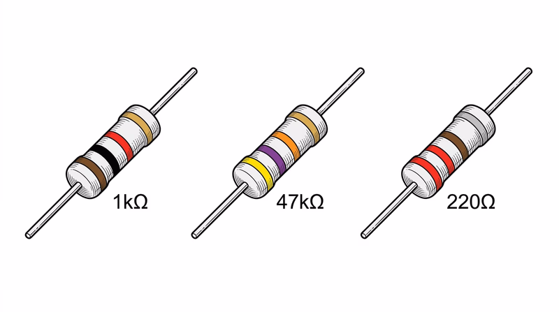
Example 1: Brown, Black, Red, Gold
- Band 1: Brown = 1
- Band 2: Black = 0
- Band 3: Red = x100
- Band 4: Gold = ±5%
Value: 10 x 100 = 1,000 ohms (1K ohm) ±5%
Example 2: Yellow, Violet, Orange, Gold
- Band 1: Yellow = 4
- Band 2: Violet = 7
- Band 3: Orange = x1,000
- Band 4: Gold = ±5%
Value: 47 x 1,000 = 47,000 ohms (47K ohm) ±5%
Example 3: Red, Red, Brown, Silver
- Band 1: Red = 2
- Band 2: Red = 2
- Band 3: Brown = x10
- Band 4: Silver = ±10%
Value: 22 x 10 = 220 ohms ±10%
5-Band Resistors
Higher-precision resistors use five bands instead of four. The first three bands are significant digits, the fourth is the multiplier, and the fifth is tolerance. For example:
Brown, Red, Green, Brown, Brown = 1, 2, 5 x 10 = 1,250 ohms ±1%
Verifying Your Reading
After reading the color code, always verify with your multimeter in resistance mode. Touch the probes to both leads and compare the displayed value to your reading. This confirms both your color-code interpretation and that the resistor has not been damaged by heat or overvoltage. You learned how to measure resistance in Req 5b.
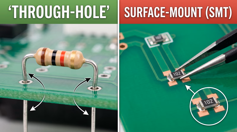
Digi-Key Resistor Color Code Calculator Interactive online tool — select band colors and see the resistance value calculated instantly. Great for double-checking your readings. Link: Digi-Key Resistor Color Code Calculator — https://www.digikey.com/en/resources/conversion-calculators/conversion-calculator-resistor-color-codeReq 5d — Through Hole vs. Surface Mount
When you built your circuit in Req 4c, you probably pushed component leads through holes in a breadboard or circuit board. That method — sticking wire leads through holes — is one of two fundamental ways to assemble electronics. The other method skips the holes entirely and mounts components directly on the surface. Each approach has distinct advantages, and understanding both gives you a fuller picture of how the electronics around you are built.
Through Hole Technology (THT)
Through Hole components have wire leads (legs) that pass through holes drilled in the circuit board. The leads poke out the other side, where they are soldered to copper pads. This is the technology you have been using throughout this badge.
How It Works
- Component leads are inserted through holes in the PCB from the top (component side).
- The leads protrude from the bottom (solder side).
- Solder is applied to the leads on the bottom, forming mechanical and electrical connections.
Three Advantages of Through Hole
Strong mechanical connections — The leads pass completely through the board and are soldered on the other side, creating joints that are physically robust. Through Hole components can withstand vibration, shock, and mechanical stress much better than surface-mounted parts. This is why Through Hole is still used in aerospace, military, and industrial equipment where reliability under harsh conditions is critical.
Easy for hand soldering and prototyping — Through Hole components are large enough to handle with your fingers, and the holes guide placement. This makes them ideal for learning, prototyping on breadboards, and hand-assembly projects — exactly the kind of work you do for this merit badge.
Simple to inspect and rework — Because the components and solder joints are relatively large, you can visually inspect them without magnification. If a joint is bad or a component needs to be replaced, desoldering and reworking is straightforward with basic tools (as you demonstrated in Req 3a).
Surface Mount Technology (SMT)
Surface Mount components sit flat on the surface of the circuit board. Instead of leads that pass through holes, they have tiny metal pads or short tabs that are soldered directly to matching pads on the board’s surface.
How It Works
- Solder paste (a mixture of tiny solder particles and flux) is applied to the board’s surface pads.
- A pick-and-place machine positions each component precisely on its pads.
- The entire board passes through a reflow oven that melts the solder paste, bonding all components simultaneously.
Three Advantages of Surface Mount
Dramatically smaller size — Surface Mount components are a fraction of the size of their Through Hole equivalents. A Through Hole resistor might be 6mm long; an SMT resistor can be smaller than a grain of sand (as small as 0.4mm x 0.2mm). This miniaturization is what makes smartphones, smartwatches, and wireless earbuds possible.
Higher component density — Because SMT components are small and can be placed on both sides of the board, engineers can pack far more components into the same board area. A modern smartphone motherboard contains thousands of components in a space smaller than a playing card.
Better high-frequency performance — SMT components have shorter electrical paths and smaller lead inductance compared to Through Hole parts. At high frequencies (radio, wireless, high-speed digital), these shorter paths reduce signal distortion and interference. This is why all modern wireless devices use SMT.
Side-by-Side Comparison
| Feature | Through Hole | Surface Mount |
|---|---|---|
| Component size | Large (millimeters to centimeters) | Tiny (fractions of a millimeter) |
| Assembly method | Hand soldering or wave solder | Solder paste + reflow oven |
| Board density | Lower | Much higher |
| Mechanical strength | Very strong | Adequate for most uses |
| Repairability | Easy with basic tools | Requires specialized tools |
| Cost at high volume | Higher (drilling holes is expensive) | Lower |
| Prototyping ease | Excellent | Difficult without equipment |
| High-frequency performance | Good | Excellent |
The Modern Reality
Today’s electronics use both technologies — often on the same board. Through Hole is used for components that need mechanical strength (connectors, large capacitors, power components) or are intended for hand assembly. Surface Mount is used for everything else. When you open a computer or game console, you will see both types working together.
IPC — Association Connecting Electronics Industries The global trade association for the electronics manufacturing industry. IPC sets the standards that define soldering quality, PCB design, and assembly methods used worldwide. Link: IPC — Association Connecting Electronics Industries — https://www.ipc.org/content-page/About-IPCReq 6 — Career Exploration
The skills you have built in this badge — reading schematics, soldering, understanding circuits, and troubleshooting — are the same foundational skills used by professionals in some of the fastest-growing and highest-paying career fields in the world. Electronics knowledge opens doors in industries as diverse as aerospace, medicine, entertainment, and renewable energy.
Three Career Paths in Electronics
1. Electrical / Electronics Engineer
Electrical engineers design the circuits, systems, and devices that power the modern world. They create everything from smartphone processors and satellite communication systems to electric vehicle drivetrains and medical imaging equipment.
What they do day to day: Design circuits using computer-aided design (CAD) software, build and test prototypes, analyze data from test equipment, write technical specifications, collaborate with manufacturing teams, and troubleshoot problems in existing products.
Education: A bachelor’s degree in electrical engineering or electronics engineering (4 years). Many engineers pursue a master’s degree for specialization. Courses include circuit analysis, signal processing, electromagnetics, digital systems, and semiconductor physics.
Certifications: A Professional Engineer (PE) license is optional but prestigious. It requires passing the Fundamentals of Engineering (FE) exam, gaining 4 years of supervised experience, and passing the PE exam. Some specializations (like power systems) strongly encourage PE licensure.
Salary range: Starting salaries for new graduates typically range from $70,000 to $90,000. Experienced engineers earn $100,000 to $150,000+, with senior and management roles exceeding $180,000 in some industries.
Job outlook: The Bureau of Labor Statistics projects steady demand for electrical engineers, with strong growth in areas like renewable energy, electric vehicles, semiconductor manufacturing, and defense systems.
2. Electronics Technician
Electronics technicians install, test, maintain, and repair electronic equipment. While engineers focus on design, technicians focus on making things work in the real world — on factory floors, in hospitals, at broadcasting stations, and inside aircraft.
What they do day to day: Use multimeters, oscilloscopes, and other test equipment to diagnose problems. Replace faulty components. Calibrate instruments. Read and interpret schematics and technical manuals. Perform preventive maintenance.
Education: An associate degree in electronics technology (2 years) or a certificate program (6-12 months). Some technicians enter the field through military electronics training. Community colleges and technical schools offer programs focused on hands-on skills.
Certifications: The Electronics Technicians Association (ETA) and ISCET (International Society of Certified Electronics Technicians) offer certifications that demonstrate competence and can increase earning potential. CompTIA A+ certification is valuable for technicians working with computers.
Salary range: Starting salaries range from $35,000 to $50,000. Experienced technicians earn $50,000 to $75,000+. Specialized technicians (avionics, biomedical equipment) often earn more.
Job outlook: Strong demand exists in healthcare (biomedical equipment technicians), telecommunications, and industrial automation. As technology becomes more complex, qualified technicians who can maintain and repair it remain essential.
3. Robotics Engineer / Embedded Systems Developer
Robotics engineers and embedded systems developers design the electronic brains inside robots, drones, autonomous vehicles, and smart devices. This field combines electronics, programming, and mechanical engineering.
What they do day to day: Program microcontrollers and processors, design sensor interfaces, develop control algorithms, test prototypes, integrate electronic systems with mechanical components, and optimize power consumption for battery-operated devices.
Education: A bachelor’s degree in electrical engineering, computer engineering, or robotics (4 years). Embedded systems work also draws from computer science. Many professionals hold master’s degrees in specialized areas like control systems or machine learning.
Certifications: While no single certification is required, skills in specific platforms (ARM microcontrollers, FPGA design, ROS for robotics) are highly valued. Demonstrating projects and open-source contributions often matters more than formal certifications in this field.
Salary range: Starting salaries range from $75,000 to $100,000. Senior embedded systems engineers and robotics specialists can earn $120,000 to $170,000+. Roles in autonomous vehicles and AI-powered robotics command premium salaries.
Job outlook: One of the fastest-growing areas in engineering. Demand is strong across manufacturing automation, autonomous vehicles, consumer electronics, medical devices, and agricultural technology.

Researching Your Chosen Career
When you pick one of these careers (or another electronics-related career you are interested in), use this framework to organize your research:
Career Research Framework
Gather this information for your counselor discussion- Training & education: What degree or program is required? How long does it take? What subjects are studied?
- Certifications: Are there professional licenses or industry certifications? What are the requirements to earn them?
- Experience: What kind of entry-level positions are available? Is an internship or apprenticeship expected?
- Expenses: What is the cost of education? Are scholarships, grants, or employer-funded training available?
- Employment prospects: How many job openings exist? Is the field growing or shrinking?
- Starting salary: What can a new graduate or newly certified professional expect to earn?
- Advancement: What does a typical career progression look like? What positions can you advance to?
- Career goals: Where could this career take you in 10-20 years?
Useful Research Sources
Bureau of Labor Statistics — Occupational Outlook Handbook Detailed career profiles including salary data, education requirements, job outlook, and work environment for electrical and electronics engineers. Link: Bureau of Labor Statistics — Occupational Outlook Handbook — https://www.bls.gov/ooh/architecture-and-engineering/electrical-and-electronics-engineers.htm IEEE — Institute of Electrical and Electronics Engineers The world's largest professional organization for electrical and electronics engineers. Offers student memberships, career resources, and information about the profession. Link: IEEE — Institute of Electrical and Electronics Engineers — https://www.ieee.org/Extended Learning
A. Congratulations, Circuit Builder
You have earned the Electronics merit badge. You can read schematics, solder and desolder components, convert between binary and decimal, apply Ohm’s law, use test equipment, and decode resistor color bands by sight. You have built a working circuit and can explain how it operates. Those skills put you ahead of most people — including many adults — when it comes to understanding the technology that surrounds us.
The sections below explore topics that go deeper than the requirements. They are here because electronics is a field where curiosity pays off, and the more you learn, the more you can build.
B. How Microcontrollers Changed Everything
The requirements of this badge cover fundamental electronics — discrete components, basic circuits, and manual soldering. But the real revolution in electronics over the past two decades has been the rise of the microcontroller: a tiny, inexpensive computer on a single chip that you can program to control almost anything.
What Is a Microcontroller?
A microcontroller is an integrated circuit that contains a processor, memory, and input/output pins — all on one chip smaller than your thumbnail. Unlike a desktop computer that runs an operating system and many programs, a microcontroller typically runs a single program that loops continuously, reading sensors and controlling outputs.
Arduino — The Gateway
The Arduino platform, launched in 2005 by a group of Italian engineers, made microcontrollers accessible to people with no engineering background. An Arduino board costs around $25 and can be programmed using free software with a simplified version of C++.
With an Arduino, you can build projects that would have required custom circuit design a generation ago:
- Weather station — Temperature, humidity, and barometric pressure sensors feeding data to an LCD display or a web dashboard.
- Automated plant watering — A moisture sensor triggers a pump when the soil gets dry, then shuts off when it is moist enough.
- MIDI controller — Buttons and potentiometers that send musical commands to a computer or synthesizer.
- Home automation — Control lights, fans, and locks from your phone using WiFi-enabled boards like the ESP32.
Beyond Arduino
Once you outgrow Arduino, an entire ecosystem awaits:
Raspberry Pi — A credit-card-sized computer that runs Linux. It can do everything an Arduino does, plus run web servers, stream video, process machine learning models, and more.
ESP32 — A low-cost microcontroller with built-in WiFi and Bluetooth, ideal for Internet of Things (IoT) projects.
Teensy — A small, fast microcontroller board popular in audio and USB projects. It can emulate a keyboard, mouse, or MIDI device.
STM32 — An industrial-grade microcontroller family used in commercial products. Learning STM32 development bridges the gap between hobbyist and professional embedded engineering.
C. The Art of Troubleshooting
Professional electronics technicians and engineers spend more time fixing broken circuits than building new ones. Troubleshooting is part detective work, part systematic reasoning, and part pattern recognition — and it is a skill that improves dramatically with practice.
The Scientific Method of Debugging
Great troubleshooters follow a process, not a hunch:
Observe — What are the symptoms? Does the circuit do nothing at all, or does it behave incorrectly? Does it work sometimes but not others? Write down exactly what you see.
Hypothesize — Based on the symptoms, what could be wrong? A circuit that is completely dead might have a power problem. A circuit that works erratically might have a loose connection or noise issue.
Test — Use your multimeter or oscilloscope to test one hypothesis at a time. Start with the simplest and most likely cause. Check power first — is the correct voltage reaching the circuit?
Isolate — Divide the circuit into sections and test each one independently. If the power supply section works, move to the next stage. This “divide and conquer” approach narrows down the problem quickly.
Fix and verify — Once you find the fault, fix it and test the entire circuit again. Sometimes fixing one problem reveals another that was hidden.
Common Failure Patterns
Experienced technicians learn to recognize patterns:
- Cold solder joints from Req 3 cause intermittent connections — they work when cool and fail when hot, or vice versa.
- Capacitor failure — Electrolytic capacitors dry out over time and lose their capacitance. This is one of the most common failures in aging electronics. Bulging or leaking caps are a telltale sign.
- Connector corrosion — Oxidation on connectors creates high-resistance junctions that cause signal loss or voltage drops.
- Thermal cycling — Components that heat up and cool down repeatedly can develop cracks in solder joints over time.
D. PCB Design — From Schematic to Product
In Req 2, you drew a schematic by hand. In Req 3c, you learned about printed circuit boards. The next step — one that many hobbyists take after earning this badge — is designing your own PCB.
The Design Process
Schematic capture — Draw your circuit in EDA (Electronic Design Automation) software like KiCad, EasyEDA, or Eagle. The software checks for electrical errors automatically.
Component footprints — Each component in your schematic is linked to a physical footprint — the exact shape and size of the pads on the PCB.
Board layout — Arrange the components on a virtual board and route the copper traces that connect them. This is like solving a puzzle — traces cannot cross on the same layer, so you need to plan carefully.
Design rule check — The software verifies that traces are wide enough for the current they carry, spaced far enough apart to prevent short circuits, and that all holes are the correct size.
Manufacturing — Export your design files and send them to a PCB fabrication house. Companies like JLCPCB and PCBWay will manufacture custom PCBs for as little as $2-5 for small boards, with turnaround times of about a week.
Assembly — When the boards arrive, you solder on your components using the skills you learned in Req 3.
Holding a PCB you designed yourself — with your name and revision number printed on the silkscreen — is one of the most satisfying experiences in electronics.

E. Real-World Experiences
Electronics Experiences to Seek Out
Hands-on opportunities to deepen your skills- Maker Faire or local maker meetup: Meet other electronics hobbyists, see projects, and learn new techniques. Many cities host regular maker events.
- Ham radio license (Technician class): Earn your amateur radio license and build your own radio equipment. The Technician license exam covers basic electronics and radio theory — topics you already know from this badge.
- Science museum or tech museum visit: Many museums have electronics exhibits with interactive circuit-building stations. The Computer History Museum in Mountain View, CA and the National Electronics Museum in Linthicum, MD are especially relevant.
- Electronics repair cafe: Community events where volunteers help people repair broken electronics. You bring your skills and learn by fixing real devices with real problems.
- Robotics competition: FIRST Robotics, VEX Robotics, and Science Olympiad all include electronics challenges. These competitions let you apply your skills in a team environment with real deadlines.