Req 2 — Reading & Drawing Schematics
This requirement covers two related tasks:
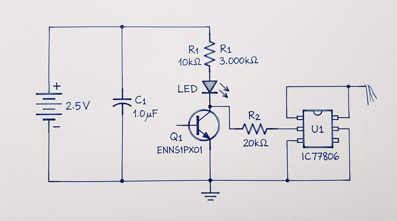
- Req 2a — Draw a simple schematic diagram with resistors, capacitors, and transistors or integrated circuits, using correct symbols and labels.
- Req 2b — Explain the purpose of each part in your schematic.
What Is a Schematic Diagram?
A schematic diagram is the blueprint of an electronic circuit. Instead of showing what a circuit physically looks like, it uses standardized symbols to show how components are connected electrically. Every engineer, technician, and hobbyist in the world reads the same symbols — a schematic drawn in Tokyo can be understood in Texas without translation.
Think of a schematic the way you think of a road map. A road map does not show every tree and building — it shows the routes and intersections you need to navigate. A schematic does the same thing for electrical pathways.
Essential Component Symbols
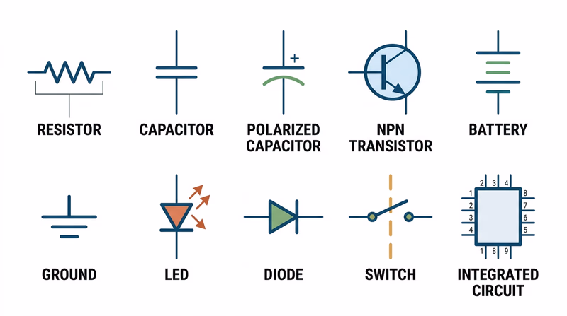
Before you can draw a schematic, you need to know the symbols. Here are the components you will use:
Resistors
Symbol: A zigzag line (US standard) or a rectangle (international standard).
Purpose: A resistor limits the flow of electrical current. It is like a narrow section of a water pipe — it slows things down. Resistors protect components from receiving too much current and divide voltage within a circuit. Resistance is measured in ohms (the symbol looks like the Greek letter omega). You will learn much more about resistors and how to read their color-coded values in Req 5c.
Capacitors
Symbol: Two parallel lines (for non-polarized) or one straight line and one curved line (for polarized/electrolytic).
Purpose: A capacitor stores electrical energy temporarily, like a tiny rechargeable battery that charges and discharges very quickly. Capacitors smooth out voltage fluctuations, filter signals, and provide bursts of energy when needed. Capacitance is measured in farads, though most capacitors you will work with are measured in microfarads (uF) or picofarads (pF).
Transistors
Symbol: A circle with three leads labeled Base (B), Collector (C), and Emitter (E). An arrow on the emitter indicates current direction (pointing outward for NPN, inward for PNP).
Purpose: A transistor is the fundamental building block of modern electronics. It works as both a switch (turning current on and off) and an amplifier (making weak signals stronger). A small current at the base controls a much larger current flowing between the collector and emitter. Billions of transistors working together inside a microprocessor make computing possible.
Integrated Circuits (ICs)
Symbol: A rectangle with numbered pins along the sides.
Purpose: An integrated circuit is a miniature circuit — sometimes containing millions of components — manufactured on a single chip of silicon. Instead of wiring up hundreds of individual transistors and resistors, you can use one IC that does the same job. Common ICs include the 555 timer (used in countless hobby projects), operational amplifiers, and microcontrollers.
Additional Symbols You Should Know
Your schematic will also need these basic symbols:
- Battery/Power Source — Long and short parallel lines (long = positive, short = negative).
- Ground — Three horizontal lines of decreasing length, or a downward-pointing triangle. Ground is the reference point for all voltages in a circuit.
- Wires — Straight lines connecting components. A dot at an intersection means the wires are connected; a small arc or bridge means they cross without connecting.
- Switch — An open gap in a line with a movable contact.
How to Draw a Schematic
Schematic Drawing Steps
Follow these steps to create a clean, readable schematic
- Start with the power source: Place the battery or power supply at the top left, with positive voltage at the top and ground at the bottom.
- Draw current flow left to right: Arrange components so the signal or current flows from left to right across the page, like reading a sentence.
- Use straight lines: Connect components with horizontal and vertical lines only — no diagonal wires.
- Label every component: Use standard designators — R1, R2 for resistors, C1, C2 for capacitors, Q1, Q2 for transistors, U1, U2 for ICs.
- Add values: Write the value next to each component — 470 ohm, 10uF, 2N2222 (a common transistor part number).
- Mark polarity: Show the positive and negative leads of polarized components (electrolytic capacitors, LEDs, diodes).
- Keep it neat: A good schematic is easy to read. Spacing, alignment, and clear labeling matter.
Explaining Your Circuit (Req 2b)
After you draw your schematic, you need to explain what each part does. Do not just name the components — describe their role in your specific circuit. For example:
- “R1 (470 ohm resistor) limits the current flowing through the LED so it does not burn out.”
- “C1 (10uF capacitor) smooths out voltage ripples from the power supply.”
- “Q1 (NPN transistor) acts as a switch — when the sensor sends a signal to the base, Q1 turns on and allows current to flow through the motor.”
The key is connecting the general purpose of each component to its specific job in the circuit you drew.