Req 3 — Soldering Techniques
This requirement covers three soldering skills you need to demonstrate:
- Req 3a — Show the right way to solder and desolder.
- Req 3b — Show how to avoid heat damage to electronic components.
- Req 3c — Explain the function of a printed circuit board and the precautions for soldering on one.
Soldering is where electronics stops being theory and becomes hands-on craft. A good solder joint creates a reliable electrical and mechanical connection that can last for decades. A bad one can cause intermittent failures that are maddening to troubleshoot. The difference comes down to technique, and technique is something you can master with practice.
Req 3a — How to Solder
What Is Soldering?
Soldering joins two metal surfaces by melting a filler metal (solder) between them. The solder — a metal alloy with a relatively low melting point — flows into the joint by capillary action and solidifies to form a strong electrical connection. Unlike welding, soldering does not melt the parts being joined.
Solder comes as a thin wire on a spool. Most hobby solder has a rosin flux core — a chemical that cleans the metal surfaces as the solder melts, allowing it to flow and bond properly.
Step-by-Step Soldering
- Prepare your iron. Turn on your soldering iron and let it heat up fully (usually 2-3 minutes). The tip should be clean and shiny.
- Tin the tip. Touch a small amount of solder to the hot tip so it is coated with a thin layer of shiny solder. This improves heat transfer. Wipe excess on a damp sponge or brass tip cleaner.
- Position the components. Insert the component leads through the circuit board holes (or position them for a wire-to-wire joint). The parts should be stable and not move during soldering.
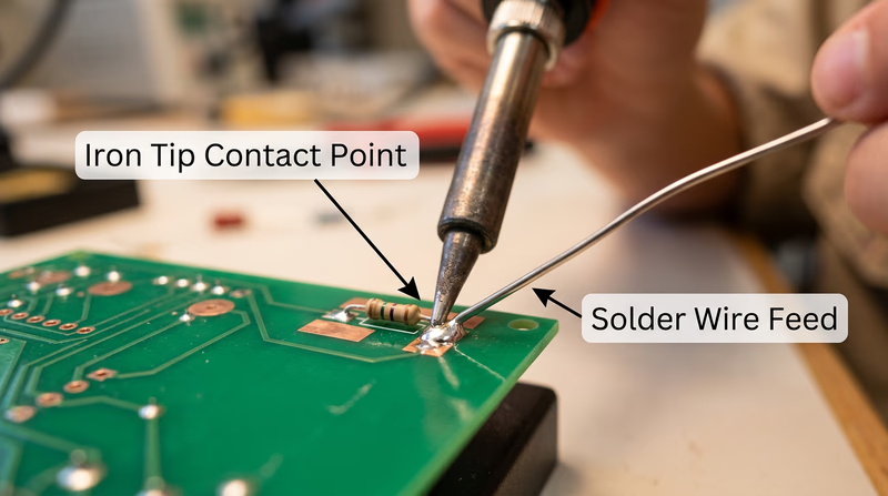
- Heat the joint, not the solder. Place the iron tip so it touches both the component lead AND the copper pad on the board simultaneously. Hold it there for 2-3 seconds to heat the joint.
- Feed solder into the joint. While the iron is still in contact, touch the solder wire to the joint (not to the iron tip). The solder should melt and flow smoothly around the lead and pad, pulled in by capillary action.
- Remove the solder, then the iron. Pull the solder wire away first, then lift the iron away. The entire process should take 3-5 seconds.
- Inspect the joint. A good solder joint looks like a small, shiny, cone-shaped mound that fully wets both the lead and the pad. It should not be a dull blob sitting on top of the pad.
Good Joints vs. Bad Joints
| Joint Type | Appearance | Cause | Fix |
|---|---|---|---|
| Good joint | Shiny, cone-shaped, smooth | Proper technique | None needed |
| Cold joint | Dull, grainy, rough surface | Joint not hot enough, or solder applied to iron instead of joint | Reheat and add flux |
| Excess solder | Large blob, may bridge to adjacent pads | Too much solder applied | Use solder wick to remove excess |
| Insufficient solder | Thin, does not fully coat the pad | Not enough solder or poor wetting | Reheat and add more solder |
| Solder bridge | Solder connects two adjacent pads that should be separate | Excess solder or pads too close | Use solder wick or desoldering pump |
How to Desolder
Mistakes happen — that is why desoldering is an essential skill. Two common tools make it possible:
Solder wick (desoldering braid) — A flat copper braid that absorbs molten solder. Place the braid over the joint, press your hot iron on top of the braid, and watch the solder wick up into the copper. Trim off the used section and repeat if needed.
Desoldering pump (solder sucker) — A spring-loaded vacuum tool. Press the plunger down to cock it, heat the solder joint until it melts, then position the pump nozzle right next to the molten solder and release the plunger. The sudden vacuum sucks the molten solder away.
Req 3b — Preventing Heat Damage
Electronic components are sensitive to heat. A transistor, IC, or LED can be permanently damaged if exposed to too much heat during soldering. Here is how to protect them:
Time Is Everything
The single most important rule: solder quickly. A good joint should take 3-5 seconds. If you are holding the iron on a joint for 10 or more seconds, something is wrong — usually the joint is not clean, or the iron is not hot enough.
Use a Heat Sink
A heat sink is a clip (often an alligator clip) that you attach to the component lead between the component body and the solder joint. The clip absorbs heat traveling up the lead, preventing it from reaching the component. This is especially important for heat-sensitive parts like transistors, diodes, and ICs.
Temperature Control
If your soldering iron has adjustable temperature, set it appropriately:
- Lead-based solder: 600-650 degrees Fahrenheit (315-345 degrees Celsius)
- Lead-free solder: 650-750 degrees Fahrenheit (345-400 degrees Celsius)
A hotter iron is not necessarily better. Higher temperatures increase the risk of heat damage and can burn the flux before it does its job.
Req 3c — Printed Circuit Boards
What Is a PCB?
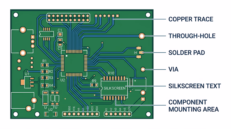
A printed circuit board (PCB) is a flat board made of fiberglass or similar insulating material with thin copper pathways — called traces — printed (etched) onto its surface. These traces replace the tangle of individual wires that would otherwise be needed to connect components. The board provides both the electrical connections and the physical structure to hold everything in place.
Modern PCBs can have multiple layers of traces sandwiched inside the board, with tiny holes called vias connecting traces on different layers. Your smartphone’s motherboard has dozens of layers packed into a board thinner than a credit card.
PCB Soldering Precautions
Soldering on a PCB requires extra care because the copper traces are thin and delicate:
- Do not overheat pads. Excessive heat can cause the copper pad to delaminate — literally peel off the board. Once a pad lifts, the board is damaged and may be unrepairable.
- Do not apply pressure. Let the solder flow naturally. Pushing the iron hard against the board can crack traces or damage the fiberglass substrate.
- Watch for solder bridges. PCB traces are close together. Excess solder can bridge across two adjacent pads or traces, creating a short circuit. Inspect your work carefully with a magnifying glass.
- Follow the silkscreen. The white printed markings on a PCB (called the silkscreen) show you where each component goes, its orientation, and its reference designator (R1, C1, Q1, etc.). Always match the component to its silkscreen marking.
- Solder in order of height. Start with the shortest components (resistors, diodes) and work up to the tallest (capacitors, connectors). This keeps components from falling out when you flip the board over to solder.