Req 4c — Build a Circuit Project
This is where everything comes together. You will choose one of three project types, find or create a schematic, build the circuit, and explain how it works. The three options are:
- A control device
- A digital circuit
- An analog circuit
Each option connects directly to the concepts you studied in Req 4a. Pick the one that interests you most — there is no advantage to choosing one over another.
Option 1: A Control Device
A control device senses a condition and responds automatically. Here are some beginner-friendly control projects:
Light-activated night light — Uses a photoresistor (light-dependent resistor) and a transistor to turn on an LED when the room gets dark. When light hits the photoresistor, its resistance drops and keeps the transistor off. In the dark, resistance rises, the transistor turns on, and the LED lights up.
Temperature-triggered fan — Uses a thermistor and a transistor to switch on a small DC fan when the temperature rises above a threshold. This is the same principle behind the cooling fan in your computer.
Moisture alarm — Two probes in the soil connect to a simple transistor circuit. When the soil is dry (high resistance), the circuit stays quiet. When water bridges the probes (low resistance), a buzzer sounds.
Option 2: A Digital Circuit
A digital circuit processes binary signals (1s and 0s) using logic gates. Beginner-friendly digital projects include:
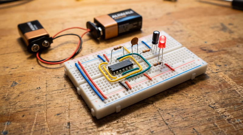
LED binary counter — Uses a 555 timer IC to generate clock pulses and a 4017 decade counter IC to light LEDs in sequence. This demonstrates how digital circuits count in a predictable, repeating pattern.
Logic gate demonstrator — Wire up AND, OR, and NOT gates using a basic logic IC (like the 7408 AND gate chip). Use switches for inputs and LEDs for outputs. You can physically see how different input combinations produce different outputs — exactly like the truth tables you studied in Req 4a.
555 timer blinker — The venerable 555 timer IC configured in astable mode generates a continuous square wave that blinks an LED on and off at a rate you control by choosing different resistor and capacitor values.
Option 3: An Analog Circuit
An analog circuit processes continuously varying signals. Good beginner analog projects include:
Audio amplifier — Uses an LM386 audio amplifier IC to boost a weak audio signal (from a phone or MP3 player) strong enough to drive a small speaker. You will hear the difference between the original quiet signal and the amplified output.
AM radio receiver — A simple crystal radio or single-transistor radio picks up AM broadcast signals using an antenna, a coil, a capacitor, and a diode. No batteries required for the simplest version — the radio signal itself provides the power.
LED brightness controller — A potentiometer (variable resistor) connected to a transistor controls LED brightness smoothly from off to full brightness. This demonstrates analog control of power.
Planning Your Project
Regardless of which option you choose, follow this process:
Circuit Project Checklist
Steps to complete your Req 4c project
- Choose your project type: Control device, digital circuit, or analog circuit.
- Find a schematic: Search online, use a book, or ask your counselor. Reliable sources include Instructables, Adafruit, SparkFun, and electronics textbook websites.
- Gather your components: Make a bill of materials listing every component and its value. Verify you have everything before starting.
- Build on a breadboard first: A breadboard lets you test your circuit without soldering. If it does not work, you can rearrange components easily.
- Test the circuit: Does it do what the schematic says it should? If not, troubleshoot. Check your wiring against the schematic, verify component values, and look for loose connections.
- Transfer to a permanent board (optional): Once it works on the breadboard, you can solder it onto a perfboard for a more permanent build.
- Prepare your explanation: Walk through the schematic and explain what each component does and how the circuit operates as a system.
Explaining Your Circuit
When you meet with your counselor, be ready to:
- Show your schematic and identify each component by its symbol and reference designator.
- Trace the signal path — follow the current from the power source through each component and explain what happens at each stage.
- Describe the purpose of each major component — not just “this is a resistor,” but “R1 limits the current to the LED so it does not exceed its 20mA rating.”
- Demonstrate that it works — power it up and show the output.
- Explain what would happen if you changed a component — for example, “if I used a larger capacitor, the blink rate would slow down.”