Model Design and Building Merit Badge — Complete Digital Resource Guide
https://merit-badge.university/merit-badges/model-design-and-building/guide/
Introduction & Overview
Overview
A model is more than a small version of something big. It is a way to test ideas, explain how parts fit together, and show other people what you are imagining before full-size work begins. In this badge, you will think like a designer, plan like a builder, and solve problems the way engineers, architects, and movie effects artists do.
Model Design and Building is also one of the most creative badges in Scouting. You can sketch by hand, design on a computer, cut parts from cardboard or wood, print pieces in plastic, and turn a rough idea into something you can hold, present, and improve. The skills you practice here matter in real jobs, but they are also useful any time you want to turn an idea into a working plan.
Then and Now
Then
People have used models for thousands of years. Builders in the ancient world made small layouts to test temple designs and city plans. Shipbuilders created scale hulls to study how a vessel might move through water before spending huge amounts of money on a full-size build. Military leaders used terrain models to explain battle plans, and inventors built prototypes to prove a machine could work before asking anyone to invest in it.
As architecture and engineering became more precise, models became more exact too. Drafting tables, rulers, triangles, and careful scale drawings let builders move from rough sketches to detailed plans. A strong model could show not just how something looked, but how it stood up, how water moved through it, or how gears might transfer motion.
Now
Today, models still do all of those jobs, but modern tools make them faster and more flexible. Architects use digital models to test room layouts, sunlight, and materials. Engineers simulate forces before they cut the first piece of material. Product designers build rapid prototypes with 3D printers and laser cutters. Special-effects artists combine real miniatures with computer-generated imagery to create worlds that feel believable on screen.
Even with all that technology, the same core questions still matter: Is the scale right? Do the parts fit? Is the structure strong enough? Does the design solve the problem it was meant to solve? This badge helps you answer those questions with both traditional hands-on skills and computer-assisted design.
Get Ready!
Bring curiosity, patience, and a willingness to revise. Good models rarely come out perfect on the first try. The fun of this badge is learning how to improve an idea step by step until it works better and looks better too.
Kinds of Model Design and Building
Display Models
Some models are built mainly to help people see an idea. An architectural house model lets a viewer understand shape, size, and layout at a glance. A fantasy spacecraft model helps a movie designer pitch a believable vehicle before cameras ever roll.
Working Models
Other models show how something functions. A plumbing model can show where water enters, where waste leaves, and how vents keep the system working properly. A mechanical model can prove that levers, pulleys, or gears really move the way the designer expects.
Structural Models
A structural model focuses on what holds everything up. Instead of pretty details, it highlights framing members, supports, joints, and load paths. These are especially useful when you want to explain why a structure is strong.
Digital Models
A digital model lives on a screen first. You can rotate it, change dimensions, test different parts, and sometimes send it directly to a printer, laser cutter, or CNC tool. Digital work is powerful, but it still depends on the same design habits as physical modelmaking: careful planning, clear measurements, and safe use of tools.
Cooper Hewitt Smithsonian Design Museum Collection Explore design drawings, objects, and models to see how professionals communicate ideas visually. Link: Cooper Hewitt Smithsonian Design Museum Collection — https://collection.cooperhewitt.org/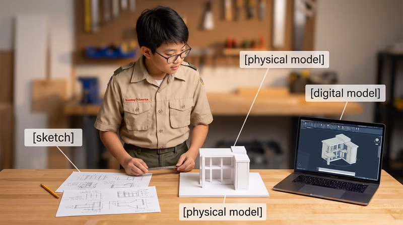
You have seen what models are for. Next, start with the rule that matters before every cut, print, and assembly step: work safely.
Req 1 — Safe Modelmaking
This requirement covers three safety areas you will use again and again in this badge: protecting your body while using hand tools, protecting your work and files while using digital tools, and protecting everyone nearby when heat, fumes, flammable liquids, or dust are involved. If you learn one habit from this badge, let it be this: do not begin a step until you understand the hazard.
Three Safety Questions
Ask these before you begin any modelmaking step- What can hurt me? Sharp edges, hot surfaces, flying chips, dust, fumes, or moving parts.
- What keeps that from happening? Safe technique, guards, ventilation, clamps, and proper protective equipment.
- What do I do if something goes wrong? Stop the tool, move to a safe position, and get an adult right away.
Requirement 1a
A hobby knife can slip. A razor saw can jump out of a cut. Sanding can send tiny particles into your eyes. That is why modelmaking safety begins with body position, tool control, and the right protective equipment.
The first rule is simple: use the right tool for the job. Do not force a dull knife to act like a sharp one. Do not use scissors where a saw or snips are needed. A tool used the wrong way makes more mistakes and causes more injuries.
Set up your work so the material cannot slide around. Use a cutting mat, clamps, or a bench hook when needed. Keep your non-cutting hand out of the blade path. When possible, cut away from your body and make several light passes instead of one hard push. Light passes give you better control and reduce the chance that the blade will suddenly break through.
Protective equipment depends on the task. Safety glasses are a smart default any time you are cutting, drilling, sanding, snapping brittle material, or trimming wire. A dust mask or respirator may be needed if an adult has approved work that creates fine dust or fumes. Closed-toe shoes protect your feet from dropped tools and materials. Gloves are useful for some tasks, such as handling rough material, but they should not be worn around spinning tools unless the tool manual and supervising adult say they are safe there.
Good housekeeping is part of personal safety too. A cluttered bench hides blades, tangles cords, and makes spills more likely. Put caps back on markers and glue bottles. Store knives with blades retracted or covered. Sweep up scraps before they become slipping hazards.
Requirement 1b
Digital work can feel safer because you are using a mouse and keyboard, but digital design still has real risks. Some of those risks are to your files, some are to the machine, and some become physical the moment a design goes to a printer, cutter, or other fabrication tool.
Start with file safety. Save your work often, name files clearly, and keep versions when you make major changes. If you overwrite a good file with a bad edit, you can lose hours of work. Check units every time you begin a design. A part drawn in inches but exported as millimeters can come out far too large or too small.
Next comes machine safety. Digital fabrication tools follow instructions exactly, even if the design is wrong. Before you print or cut, check scale, wall thickness, clearances, and material choice. Use preview tools to spot unsupported parts, collisions, or impossible cuts. Make sure the software settings match the real machine and material you are using.
Digital tools also create physical hazards. A 3D printer has hot nozzles and heated beds. A laser cutter can start a fire if the material is wrong or the machine is left unattended. Moving gantries and belts can pinch fingers. Ventilation matters because some plastics, glues, and coatings release fumes when heated.
Finally, practice responsible digital behavior. Use approved software, follow your maker space or school lab rules, and do not download random files just because they look useful. If you borrow a design element, understand its license and give credit when appropriate. For this badge, your main project must still be your own original design.
Requirement 1c
Many modelmaking materials are useful because they dry fast, bond strongly, melt easily, or cut cleanly. Those same qualities can create hazards. Spray paint, solvent-based cement, resin, some cleaners, and certain plastics can be flammable, irritating, or unsafe to breathe.
Read the label before you open the container. If a material says to use it outdoors or with strong ventilation, follow that instruction exactly. Keep flammable products away from open flames, heaters, sparks, and anything that gets hot. That includes soldering tools, heat guns, and even a laser cutter that is being used on the wrong material.
Only use the amount you need. Leaving a whole bottle open increases fumes and spill risk. Cap containers promptly and store them in their original containers so the safety information stays with them. Never mix chemicals unless the instructions specifically say it is safe.
Protect your skin and eyes when required. Some adhesives bond skin almost instantly. Resins and hardeners can irritate skin or trigger allergic reactions. Paints and solvents can splash without warning. If hazardous materials get on your skin, in your eyes, or on your clothes, tell an adult immediately and follow the product instructions.
Disposal matters too. Some scraps can go in ordinary trash, but liquids, resin waste, solvent-soaked rags, and used containers may need special handling. Ask before throwing them away.
OSHA — Hand and Power Tools A practical overview of safe tool use, guarding, and common hazards that applies well to modelmaking benches. Link: OSHA — Hand and Power Tools — https://www.osha.gov/hand-power-tools OSHA — Eye and Face Protection Clear guidance on when eye protection matters and why flying particles are a serious hazard. Link: OSHA — Eye and Face Protection — https://www.osha.gov/eye-face-protection CDC/NIOSH — 3D Printing with Filaments Safety guidance for hot surfaces, fumes, ventilation, and protective practices when using filament-based 3D printers. Link: CDC/NIOSH — 3D Printing with Filaments — https://www.cdc.gov/niosh/docs/2020-115/ OSHA — Laser Hazards A helpful summary of why lasers require controlled procedures, supervision, and eye protection. Link: OSHA — Laser Hazards — https://www.osha.gov/laser-hazards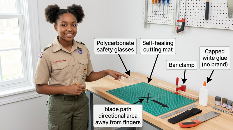
Once you know how to stay safe, you are ready to learn what different models are meant to do and which tools and materials fit each kind of project.
Req 2 — Models, Tools, and Materials
This requirement introduces the big picture. You will compare why different kinds of models exist, how traditional and digital tools help at different stages, and which materials make sense for different jobs. Once you understand those relationships, it becomes much easier to choose a project that matches your interests and skill level.
Requirement 2a
The easiest way to remember model types is to ask what question the model answers.
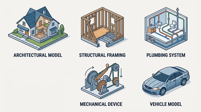
Architectural models answer, “What will this place look and feel like?” They show the shape of a building, the layout of rooms, the relationship between walls and windows, and sometimes the surrounding site. These are useful when an architect wants to explain a design to a client or compare design choices.
Structural models answer, “What keeps this thing standing?” Instead of focusing on decoration, they highlight beams, studs, rafters, joints, and supports. A structural model helps you see load paths and understand why a building resists gravity, wind, or weight.
Process models answer, “How does something move through a system?” Plumbing is a great example. A process model can show where water enters, where waste exits, and how venting supports proper flow. These models help make hidden systems easier to understand.
Mechanical models answer, “How does motion happen?” They show how levers, pulleys, gears, wedges, wheels and axles, and screws create or transfer force. A mechanical model is especially useful when a device needs to do work, not just sit on display.
Industrial models answer, “What will this product or vehicle look like in the real world?” They focus on form, proportion, user experience, and manufacturability. A vehicle model, for example, can help a designer study how the body, windows, and wheels work together as one product.
Requirement 2b
Traditional tools and digital tools often do the same jobs in different ways.
To create plans, traditional tools include graph paper, rulers, scale rules, compasses, triangles, and pencils. They teach careful measuring and help you think slowly through your layout. Digital tools let you set exact dimensions, copy repeated parts, and revise without redrawing the whole page.
To simulate function, a designer may build a quick physical mock-up from cardboard or foam to test shape and movement. Digital tools can go further by showing motion, interference, and fit before anything is built. A mechanical device can be checked for range of motion. A building model can be rotated and studied from every side.
To visualize models, hand sketches help you explore ideas quickly. Perspective sketches, elevations, and exploded views make your thinking visible. Digital tools can create clean renderings, shaded views, and multi-angle images that help other people understand what you mean.
To assist in construction, traditional tools help you mark, cut, clamp, sand, and assemble parts. Digital tools can produce templates, cut files, print files, and dimensions that reduce guesswork. A designer might sketch by hand, refine the design on a computer, print a test part, then finish the final assembly with hand tools. That mixed approach is common and smart.
Traditional vs. Digital
Both approaches are useful at different moments- Traditional tools are excellent for quick idea generation, learning scale, and hands-on problem solving.
- Digital tools are excellent for precision, revisions, repeated parts, and machine-assisted fabrication.
- Best practice is often to combine them: sketch first, model second, build third, revise as needed.
Requirement 2c
Different materials are good at different jobs. Cardboard is cheap, easy to cut, and perfect for quick mock-ups. Foam board is light and clean for architectural walls and presentation pieces. Basswood and balsa wood are common when you want strength with a finished look. Styrene sheet and rod are popular for detail work because they cut cleanly and can be shaped accurately.
Modern modelmakers also use acrylic, resin, filament for 3D printing, laser-cut sheet materials, and digital files that never become physical until the final stage. A digital material can be just as real to a designer as cardboard or wood because it controls what the machine will produce.
Fabrication methods matter just as much as the material itself. Traditional methods include measuring, scribing, scoring, cutting, sanding, drilling, gluing, and painting. Modern methods include CAD modeling, slicing for 3D printers, exporting vector paths for laser cutting, and producing renderings for presentation.
When describing methods, connect them to the goal. If you need clean repeated window openings, laser cutting might help. If you want to test a rough shape fast, cardboard and hot glue may be better. If you need a curved engine housing for a fantasy spacecraft, digital modeling and 3D printing might save time.
🎬 Video: CardBoard Basics Tutorial Guide Chip/Matte Board model making: modeling for Designers & Architects — Eric Strebel — https://www.youtube.com/watch?v=x6s3lGH4MyI
You now know what kinds of models exist and what tools support them. The next step is choosing your own project and planning it carefully enough that the build can succeed.
Req 3 — Planning Your Original Project
This parent requirement matters because it turns your build from a cool idea into a workable plan. Before you start cutting material or opening software, decide what you are making, why it interests you, what scale it will use, and which tools you actually have access to. A strong plan saves material, prevents frustration, and makes your counselor conversation much more productive.
Your project must be your own original design. That does not mean every part has to come from nowhere. You can study real houses, real plumbing layouts, real vehicles, or real machines for inspiration. What matters is that you are making design choices yourself instead of assembling a premade kit someone else already solved.
Project Planning Worksheet Resource: Project Planning Worksheet — /merit-badges/model-design-and-building/guide/project-planning-worksheet/Requirement 3a
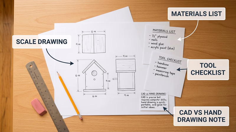
A scale drawing is the bridge between your idea and your build. It tells you how big each part should be and how those parts relate to each other. Without a scale plan, modelmaking turns into guessing.
Start by choosing the required scale from the option you plan to build in Req 4. Write that scale at the top of every sketch or digital drawing. Then draw the main views your project needs. A house may need floor plans and elevations. A vehicle may need top, front, rear, and side views. A mechanical device may need an overall view plus close-ups of moving parts.
Use clear dimensions even if your drawing is not perfect art. Straight lines, labels, and measurements matter more than fancy shading. If you are working digitally, double-check your units before printing or exporting. If you are drawing by hand, use a ruler and keep a conversion note nearby so you can translate full-size dimensions into model size.
What a Good Plan Shows
Include enough information that you could build from it later- Overall size: Length, width, height, or footprint.
- Key views: Top, side, front, section, or elevation as needed.
- Important parts: Doors, windows, framing members, pipes, wheels, gears, or other major features.
- Scale note: The ratio or drawing scale written clearly on the page.
- Labels: Part names so your counselor can follow your thinking.
Requirement 3b
A materials list should do more than name what you hope to use. It should explain what each material is for and how much you need. That keeps you from buying too much, forgetting a critical piece, or choosing a material that does not match the job.
For each item, list the material, size or thickness, estimated quantity, and purpose. For example, foam board might form wall panels, clear plastic might become windows, and basswood strips might become framing members. If you are using a digital method, include filament type, print color, resin, acrylic sheet, or laser-cut stock.
Think about finish materials too. Paint, primer, glue, sandpaper, and labels are all part of the project. A model often stalls because the builder planned the big pieces but forgot the adhesives and finishing supplies.
A smart materials list answers four questions
- What is this item? Cardboard, styrene, PLA filament, basswood, acrylic, and so on.
- How much do I need? Sheets, sticks, feet, pieces, or grams.
- Why this material? Strength, appearance, flexibility, clean cuts, low cost, or easy printing.
- What is the backup plan? If that material is unavailable, what could replace it?
Requirement 3c
Your tool list should match your design honestly. If your project needs a drill, clamps, hobby knife, square, cutting mat, sanding block, and paintbrushes, list them. If it needs a computer, CAD software, 3D printer, calipers, or a laser cutter supervised by an adult, list those too.
This requirement is really about planning the build process. A tool list helps you notice early if your design depends on equipment you do not actually have. It is much better to revise the design now than to discover halfway through that one missing tool makes the project impossible.
Requirement 3d
Your counselor wants to hear your reason, not the “right” answer. Maybe you chose a house model because you like architecture. Maybe you chose a structural corner because you want to understand how buildings really stand up. Maybe a fantasy spacecraft gives you room to be inventive.
A strong explanation connects your choice to one or more of these ideas:
- Personal interest: You genuinely enjoy the subject.
- Learning goal: You want to understand a real system or design method.
- Challenge level: The project stretches you without overwhelming you.
- Resources available: You can actually build it with the tools and materials you have.
When you explain why you chose the subject, show that you made the decision on purpose. That proves this is your project, not just the first option you saw.
Requirement 3e
You do not have to use computer tools for every project, but you should think seriously about where they help. Digital tools are great for repeated parts, precise dimensions, and trying out changes without wasting material. Hand methods are great for quick sketching, direct problem solving, and working with simple materials on a bench.
The smartest answer is often a blended one. You might sketch early ideas by hand, create final dimensions on a computer, print a template, and then build the model physically. Or you might do the reverse: start with a rough cardboard mock-up to test proportions, then redraw the best version digitally.
Talk with your counselor about your actual plan. Which steps will be traditional? Which steps might benefit from CAD, 3D modeling, digital rendering, or machine-assisted fabrication? How will using those tools make your build clearer, more accurate, or easier to revise?
🎬 Video: How To Think Like An Architect: The Design Process — Barry Berkus — https://www.youtube.com/watch?v=vmHoGicPQQQ
By now, you should have a project idea that is scaled, supplied, and realistic. Next, compare the five build paths and decide which one you will make.
Req 4 — Pick Your Model Path
You must choose exactly one option from this requirement. Each path teaches the same design habits — planning, scale, material choice, and revision — but each one emphasizes a different kind of thinking.
Your Options
- Req 4a — House in Miniature: Design a scaled house model with floor plans, elevations, doors, windows, and exterior details. You will practice layout, proportion, and presentation.
- Req 4b — Showing How a Building Stands: Build a framing-corner model that highlights studs, joists, rafters, and other structural parts. You will learn how buildings carry weight and stay rigid.
- Req 4c — Mapping Water In and Waste Out: Model a house plumbing system with supply lines, drains, and venting. You will learn to think in systems and flow paths.
- Req 4d — Motion with Simple Machines: Build a working device that uses at least two simple machines. You will focus on force, motion, and function.
- Req 4e — Designing a Scaled Passenger Vehicle: Measure a real vehicle and turn those observations into a scaled model. You will practice proportion, exterior form, and multi-view drawing.
How to Choose
Choosing Your Option
Compare the kind of work each project asks you to do- Time and detail: The architectural and vehicle options often require lots of visible detail. The structural and mechanical options can be more focused if you want to show function clearly.
- Best for hands-on building: The structural and mechanical options are especially good if you want to cut, assemble, and test parts physically.
- Best for systems thinking: The plumbing process model is strong if you like understanding how hidden systems connect and flow.
- Best for visual design: The architectural and vehicle options are ideal if you enjoy shape, appearance, and presentation from multiple views.
- What you will gain: Architectural work builds design communication, structural work builds construction understanding, process work builds system mapping, mechanical work builds motion and problem solving, and vehicle work builds proportion and industrial-design thinking.
| Option | Main focus | Good choice if you enjoy… | Main challenge |
|---|---|---|---|
| 4a Architectural | Space, layout, appearance | Houses, room design, presentation models | Keeping scale and details consistent |
| 4b Structural | Framing and support | Construction, how things stand up | Making the skeleton clear and accurate |
| 4c Process | Systems and flow | Plumbing, diagrams, hidden systems | Keeping all lines readable |
| 4d Mechanical | Motion and force | Gadgets, moving parts, testing ideas | Getting the device to work smoothly |
| 4e Industrial | Form and proportion | Cars, vans, buses, exterior styling | Translating measurements into clean model views |
🎬 Video: New to Scale Modeling? Avoid These Five Beginner Mistakes! — SpruesNBrews Scale Modeling — https://www.youtube.com/watch?v=tn2SnnhHoLo
The first option is the architectural model. Even if you end up choosing a different build path, reading through one option carefully can help you understand the level of planning your own project will need.
Req 4a — House in Miniature
An architectural model is your chance to think like both a designer and a storyteller. A good house model does not just show walls and a roof. It helps your counselor understand how the house is organized, what the outside feels like, and how carefully you can turn two-dimensional drawings into a clean three-dimensional object.
At 1:48 scale, every decision matters. A full-size doorway, window, roofline, porch, or chimney becomes much smaller, so you have to simplify without losing the character of the design. That balance between accuracy and readability is one of the most important skills in architectural modelmaking.
Start with Plans and Elevations
Before you build, draw the house from more than one view. A floor plan shows the arrangement of rooms and walls as if you sliced the house horizontally and looked down. Elevations show the outside faces of the building — front, rear, and sides. Together, these drawings tell you where doors, windows, roof edges, and wall heights belong.
If you skip this step, your model will usually start drifting. One wall will end up longer than another. A roof angle will not meet cleanly. Windows will line up on one side but not the other. Plans keep the project honest.
Architectural Plan Essentials
Make sure your drawings include these items- Floor plan: Exterior walls, interior walls if used, door swings, and major openings.
- Elevations: Front and side views with roof shapes and window placement.
- Scale note: Clearly mark 1:48 on every drawing.
- Major dimensions: Overall length, width, wall height, and key opening sizes.
Choose Materials That Fit the Look
Architectural models are often judged by neatness. Foam board, illustration board, basswood, mat board, and styrene are popular because they create straight edges and clean planes. Clear plastic sheet can stand in for glass. Textured paper, painted card, or 3D printed parts can add shingles, doors, trim, or other details.
The best material choice depends on what you want to show. If the main goal is the shape and layout of the house, simple flat materials may be enough. If you want your model to feel more realistic, you can add exterior treatment such as sidewalks, shrubs, steps, fencing, or paint. Just do not let decoration hide poor scale control.
Include Structural Thinking
Even though this is an architectural model, the requirement also asks you to include structural elements. That means you should think about what holds the house together, not just what it looks like from the curb. Roof supports, wall thickness, floor alignment, and major framing ideas should make sense.
You do not need to expose every stud unless you want to, but your design should show that doors, windows, and walls are arranged in a believable way. A model becomes much stronger when appearance and structure support each other.
Outside Treatment and Color
Small details help a house model feel finished. A walkway shows how someone approaches the home. Shrubbery suggests scale and site layout. Paint or colored materials can separate roof, siding, trim, and foundation. Keep these choices simple and consistent. A few well-placed details usually look better than too many tiny decorations competing for attention.
If you are using computer tools, this is also where they can help. You might laser-cut repeated windows or 3D print a porch column set. Just make sure those parts still fit the same scale and style as the rest of the model.
Cooper Hewitt Smithsonian Design Museum Collection A rich source of design drawings and presentation ideas that can help you see how professionals communicate form and proportion. Link: Cooper Hewitt Smithsonian Design Museum Collection — https://collection.cooperhewitt.org/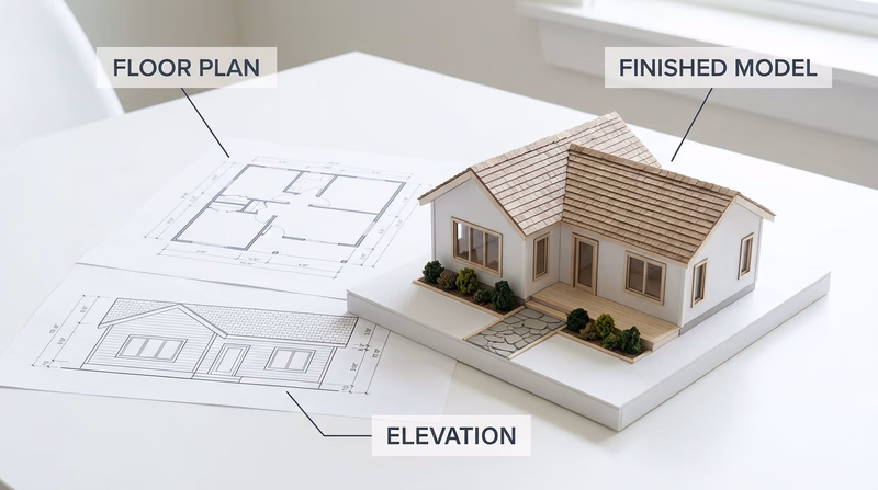
If you want to focus less on appearance and more on what keeps a building standing, the structural model takes you inside the skeleton of construction.
Req 4b — Showing How a Building Stands
This option is less about decoration and more about understanding the hidden skeleton of a building. A structural corner model lets you show how floor framing, wall framing, and roof framing connect to make a building strong. At 1:8 scale, the parts are large enough to label clearly and build with care.
The big question behind this project is simple: where does the load go? Roof weight travels into rafters, down through studs, and into the framing below. A good structural model helps your counselor see that path clearly.
Know the Main Parts
You do not need to memorize terms without understanding them. Instead, picture what each one does.
- Intermediate girder: A major horizontal support that carries floor loads.
- Joist: A repeating horizontal member that supports the floor.
- Bridging: Bracing between joists that helps keep them aligned and stable.
- Subfloor: The layer attached over the joists that creates the floor surface base.
- Sill: The member that rests on the foundation and connects framing to the base.
- Sole plate: The bottom horizontal piece of a wall frame where studs are attached.
- Stud: Vertical wall framing member.
- Rafter: Sloped roof framing member that carries roof loads downward.
If you can point to each part on your model and explain its job, you are doing the real learning this requirement is after.
Use a Clean Structural Layout
Before building, make a drawing that shows where each framing member belongs. Because this is a corner model, you are not building a whole house. You are building enough of one corner to explain how the pieces meet. That means clarity matters more than size.
A helpful layout usually shows floor framing below, wall framing above, and a roof section on top. Think about spacing. If members are too crowded, your model becomes hard to read. If they are too sparse, it stops looking believable.
🎬 Video: How To Build a Deck | Design & Layout (1 of 5) — Lowe's Home Improvement — https://www.youtube.com/watch?v=v79flY1pIKk
Structural Model Goals
Aim for these qualities in your build- Accurate part relationships: Floor, wall, and roof members connect where they should.
- Readable spacing: The viewer can easily distinguish one component from another.
- Stable assembly: The model stands and holds shape without twisting.
- Clear explanation: You can name each part and explain its purpose.
Material Choices
Wood is a natural choice because it behaves like the real material the model represents, but cardboard and foam board can work well if cut carefully. Whatever you choose, straight cuts and square joints are important. Crooked members make the structure harder to understand.
A good trick is to prepare repeated pieces in batches. Cut all similar studs together, all joists together, and all rafters together. That keeps sizes consistent and saves time during assembly.
Common Challenges
One common challenge is keeping everything square. If the corner is out of square early, every part added later becomes harder to fit. Another is choosing enough detail without overcrowding the model. You want the model to teach, not confuse.
Support can also be tricky. Real buildings rely on many connected parts. Your model may need temporary braces during assembly or a sturdy base to keep the framing aligned while glue dries.
American Wood Council — Wood Frame Construction Resources A professional reference that helps explain wood framing members and how structural parts work together in real buildings. Link: American Wood Council — Wood Frame Construction Resources — https://www.awc.org/codes-standards/publications/wcd1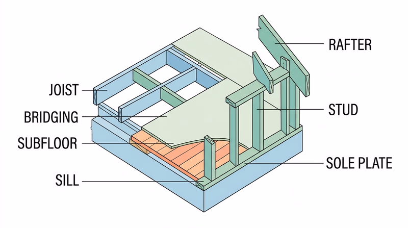
If you like the idea of showing a hidden system instead of a visible structure, the process model moves from framing to flow.
Req 4c — Mapping Water In and Waste Out
A process model helps people understand a system that is usually hidden behind walls. In a plumbing model, the goal is not to make a pretty miniature bathroom. The goal is to show where water enters, where it travels, how waste leaves, and how venting keeps the system working.
That makes this option great for Scouts who like diagrams, systems thinking, and explaining how several connected parts do one job together.
Separate the Three Main Paths
A good plumbing model clearly distinguishes three different things.
Cold-water supply brings fresh water into fixtures such as sinks, toilets, showers, and appliances. Hot-water supply starts at the water heater and serves the fixtures that need heated water. Waste returns carry used water away. Vents connect the drainage system to air so water can flow properly without creating suction problems.
If those lines all look the same, the model becomes hard to read. Use color, labels, spacing, or different material sizes so each kind of line is easy to follow.
What Your Plumbing Model Must Show
Make each system easy to trace with your eyes- Cold-water supply: A clear route from source to fixtures.
- Hot-water supply: A separate path from heater to fixtures that need it.
- Waste returns: Drain lines carrying used water out.
- Venting: Pipes that support drainage by letting air into the system.
Plan Before You Build
Start with a simple house layout. Mark fixture locations first, then connect them with supply and drain paths. You do not need to copy every pipe in a real house. You do need to show the logic of the system clearly.
At 1:16 scale, readability matters more than tiny detail. If pipes overlap too much, viewers will lose the system. It is often better to space parts slightly for clarity while still keeping the model believable.
Good Materials for System Models
This option works well with straws, tubing, wire, dowels, or printed parts because those materials naturally suggest pipe runs. Foam board or cardboard can become floors and walls if you want some building context around the system. You can also mount the whole model on a board so the pipes remain visible and stable.
If you use computer tools, they can help you lay out clean pipe routes, test spacing, or print connectors and fixtures. Just remember that the finished result still needs to communicate the system clearly to another person.
Problems You May Run Into
The most common challenge is crowding. Real plumbing lines pass through framing and change direction often. In a model, that can turn into a tangle. Another challenge is keeping the vent system visible. Because vents are less obvious than supply or waste lines, they are easy to forget even though the requirement specifically asks for them.
Think about the order of assembly. If you glue the outer walls too early, you may block access to the system you are trying to show. Many process models work best when the system stays partly exposed.
EPA WaterSense Homes Helpful background on how plumbing systems are planned in real homes, especially around fixtures, water use, and system layout. Link: EPA WaterSense Homes — https://www.epa.gov/watersense/homes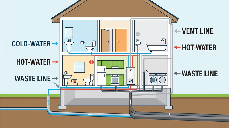
If you would rather build something that moves instead of something that flows, the mechanical model gives you a chance to turn force into action.
Req 4d — Motion with Simple Machines
This option is about function first. Your model is not finished just because it looks interesting. It should actually do something, and that means your design has to move, transfer force, lift, guide, rotate, or otherwise perform a task in a repeatable way.
The requirement says to use at least two of the six simple machines: lever, wheel and axle, pulley, inclined plane, wedge, and screw. The easiest way to succeed is to choose a device where those simple machines naturally belong together.
Pick a Device with a Clear Job
A mechanical model works best when it has one simple purpose. Maybe it lifts a small weight, moves an object along a short path, turns one motion into another, or presses one part against another. If the job is clear, you can judge whether the design actually works.
Examples might include a small lifting device, a hand-cranked winch, a drawbridge mechanism, or a simple transfer system. Your exact design should be your own, but the principle is the same: one motion causes another motion in a controlled way.
Use the Simple Machines on Purpose
Do not add a simple machine just to check a box. Show how each one contributes to the design.
- A lever can multiply force or change the direction of effort.
- A wheel and axle can make turning easier or transfer rotational motion.
- A pulley can redirect force and help lift loads.
- An inclined plane can trade distance for easier lifting.
- A wedge can separate, guide, or hold parts in place.
- A screw can fasten parts or convert rotation into forward motion.
When you present your project, explain not only which simple machines you used, but why those choices make the device work.
Mechanical Model Success
A working model should show these things clearly- Function: The device performs a repeatable action.
- Two simple machines: Both are easy to identify and explain.
- Stable construction: Parts stay aligned while moving.
- Clear force path: You can show where effort goes and what result it creates.
Design, Test, Revise
Mechanical models almost always need adjustment. Axles may bind. Pulleys may wobble. A lever arm may be too short. Printed parts may fit differently than expected. That is normal. In fact, revision is one of the main lessons of this option.
If you use digital tools, simulate fit and movement before building. But even a well-designed digital model still needs real-world testing because friction, loose joints, and material flex can change the result.
Materials and Construction Choices
Wood is strong and easy to modify. Plastic sheet can make clean parts. 3D printing is excellent for custom wheels, housings, or brackets. Hardware-store items such as dowels, washers, string, rubber bands, and screws can also be useful if they fit your original design.
Whatever you choose, avoid hidden shortcuts. If one part needs support, redesign it or reinforce it honestly. A mechanical model is supposed to prove that the arrangement works, not hide weak points with last-second fixes no one can understand.
NASA Glenn — Beginners Guide to Rockets A useful example of how engineers break complex motion and force problems into understandable systems and testable models. Link: NASA Glenn — Beginners Guide to Rockets — https://www.grc.nasa.gov/www/k-12/rocket/guided.htm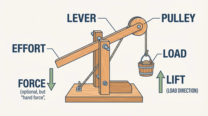
If you like shape and proportion more than moving parts, the industrial vehicle model lets you study a real object from every angle and turn it into a scaled design.
Req 4e — Designing a Scaled Passenger Vehicle
This option trains your eye. Vehicles are full of curves, proportions, and repeated shapes that look simple until you try to draw them accurately. The challenge is not just building a miniature car, van, or bus. It is learning to observe the real vehicle closely enough that your scaled version still feels like the same machine.
Measure the Real Vehicle Carefully
The requirement specifically tells you to begin by measuring a real passenger-carrying vehicle. That step matters because real measurements keep the project grounded in reality. Record overall length, width, height, wheelbase if possible, wheel size, and the positions of major features such as doors, windows, lights, and bumpers.
Then turn those measurements into scaled dimensions. Once you choose 1:12 or 1:24, stay consistent. A model where the body is at one scale and the wheels are at another will look wrong even if each part is neat on its own.
Use Multiple Views
Vehicle design depends on seeing the object from several directions at once. A side view shows overall length, roofline, and wheel spacing. A front view shows width and stance. A top view reveals the footprint and windshield angle. Rear views help with symmetry and tail details.
When those views agree with each other, your final model becomes much easier to build. When they do not, the body shape starts to drift.
Vehicle Drawing Set
These views make a strong starting point- Side view: Overall profile, wheels, doors, and roofline.
- Front view: Width, headlights, grille, and windshield shape.
- Rear view: Symmetry, trunk or hatch, and light placement.
- Top view: Body footprint, hood, roof, and window arrangement.
Choose What Level of Detail You Can Finish
It is easy to get excited and plan every mirror, door handle, and trim line. But a strong model often comes from choosing the most important features and doing them well. Start with overall body proportions, wheel placement, and window shapes. Those three things usually determine whether a viewer recognizes the vehicle immediately.
Once the big shapes are right, add selected details that support the identity of the vehicle. Maybe it is the grille, the body crease, the wheel arches, or the shape of the rear lights. Prioritize the details that say, “This is definitely that vehicle.”
Physical Build or Digital Final
This option gives you flexibility. You can build a physical model by hand, produce a digital rendering, 3D print the body, or combine methods. A smart mixed approach might be to sketch and measure by hand, refine the shape digitally, print small test sections, and then complete the final version physically.
Your counselor will also want to hear which parts were hardest. That reflection is valuable because vehicle design involves compromise. Curved surfaces, wheel openings, windshield angles, and symmetry are all common trouble spots.
NASA Glenn — Beginners Guide to Aeronautics Even though it focuses on aircraft, it is a strong example of how real designers study shape, drag, and multiple-view geometry when creating vehicles. Link: NASA Glenn — Beginners Guide to Aeronautics — https://www1.grc.nasa.gov/beginners-guide-to-aeronautics/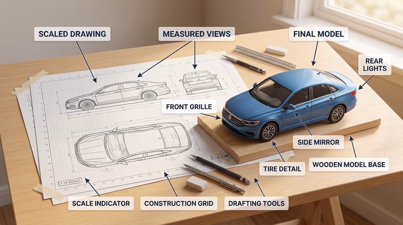
You have now reviewed all five build choices. The next requirement shifts from real-world models to something more imaginative: a fantasy spacecraft built with believable design logic.
Req 5 — Designing for the Big Screen
This requirement takes everything you learned about real models and pushes it into imaginative design. Even though the spacecraft is fictional, it still needs to feel believable. That usually happens when the design borrows logic from real machines: clear purpose, sensible scale, visible systems, and shapes that look like they could actually operate.
You are not just doodling a spaceship. You are designing a vehicle for a film audience that will instantly ask, “What does that part do?” and “Could that thing really exist?”
Requirement 5a
The best fantasy spacecraft designs usually have a backbone of real engineering. Aircraft teach you about control surfaces, cockpit visibility, engines, and lightweight structure. Submarines teach pressure-hull thinking, tight interior planning, and the idea that external shape often follows mission. Naval ships teach deck arrangement, mass, layered systems, and how a large vehicle announces its purpose from far away.
As you research, look for patterns instead of trying to copy one vehicle exactly. Where are the crew spaces? Where are engines or propulsion systems located? What parts need access? What shapes look fast, stable, heavy, stealthy, or exploratory?
Requirement 5b
Break the spacecraft into functional zones. A cockpit is about visibility, controls, and crew access. Living areas are about rest, movement, and limited space. Engines are about power, heat, and thrust. Storage is about mission needs: cargo, supplies, tools, fuel, or escape gear.
Thinking in components keeps the design from becoming one vague shell. Even if your final model is small, the audience should feel like the ship has a real interior logic. Ask yourself where the crew enters, how they move through the craft, and what the ship is built to do. Is it a scout? A freighter? A patrol ship? A scientific survey craft? The mission should shape the design.
Designing Components
Give each major area a reason to exist- Cockpit: Who sits there and what must they see?
- Living area: How does the crew eat, sleep, or work on long trips?
- Engines: Where does thrust come from and where does heat go?
- Storage: What must the ship carry for its mission?
Requirement 5c
This step turns your ideas into something another person can evaluate. Multiple angles are important because a great side view can hide a weak top view, and a cool front silhouette may not make sense from the rear.
Your final presentation should show enough views that the whole design feels consistent. Common choices are front, side, top, and three-quarter perspective. If you work digitally, use rendered views with clear lighting. If you work by hand, focus on clean lines, consistent shapes, and labels where useful.
Requirement 5d
This final discussion is where you prove that your design was thoughtful. Explain how your research influenced your choices, why the scale makes sense, which materials or software you used, and how you solved problems along the way.
A practical scale is one that lets you show the main forms and important details without creating a model too large to build or too small to understand. Your engineering choices should also make sense. Maybe you used foam board for the body shell, printed engine housings, and styrene for surface detail. Maybe you stayed fully digital and used rendering tools to communicate materials, lighting, and surface texture.
The difficulties you mention are often the most interesting part. Maybe the engines overwhelmed the body shape. Maybe the cockpit looked too small for the crew. Maybe the ship looked exciting from one view but awkward from another. Those revisions are not proof of failure. They are proof that you designed, tested, and improved.
NASA Glenn — Beginners Guide to Aeronautics A strong source for studying real vehicle design logic, propulsion ideas, and shape decisions that can inspire more believable fantasy spacecraft. Link: NASA Glenn — Beginners Guide to Aeronautics — https://www1.grc.nasa.gov/beginners-guide-to-aeronautics/ Stanford d.school — Design Thinking Bootleg Useful for understanding how professional designers iterate, test ideas, and improve a concept through multiple revisions. Link: Stanford d.school — Design Thinking Bootleg — https://dschool.stanford.edu/resources/design-thinking-bootleg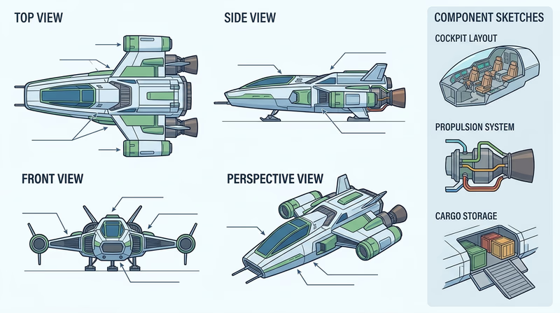
You have explored both practical and imaginative model design. The final requirement asks you to look beyond the badge at careers where these same skills matter every day.
Req 6 — Careers in Design and Building
This requirement helps you connect hobby skills to real jobs. The same habits you used in this badge — planning, scale drawing, digital modeling, prototyping, testing, and explaining your choices — are valuable in many careers. Some of those careers focus on buildings, some on products, some on machines, and some on entertainment design.
Careers You Might Explore
Here are several strong choices connected to this badge:
- Architect — designs buildings and spaces, often using drawings, models, and digital visualization.
- Architectural drafter — produces detailed drawings that builders and designers use to turn ideas into construction documents.
- Mechanical engineer — designs machines, systems, and moving parts.
- Mechanical drafter — creates precise drawings and technical plans for manufactured parts and devices.
- Industrial designer — shapes products and vehicles so they are useful, attractive, and manufacturable.
- Model maker or prototype technician — builds physical versions of designs for testing, presentation, or entertainment.
What to Research
Your counselor wants more than a job title. Build a short research profile that covers these categories clearly.
Training and education
Does the career usually require a high school diploma, technical program, associate degree, bachelor’s degree, or professional license? Some design jobs require a college degree. Others can begin through technical training and strong portfolio work.
Costs
Think about tuition, software training, certifications, tools, and internships. A career path is easier to understand when you know not just what training is needed, but what it may cost.
Job prospects and salary
Look for whether the field is growing, stable, or competitive. Salary should be one part of the picture, not the whole picture. A job that pays well but does not fit your interests may not be satisfying.
Job duties and advancement
What does the person actually do during a normal week? Do they sketch, model, revise plans, talk with clients, test prototypes, or coordinate with builders? What kinds of roles can they move into later?
Career Research Questions
Bring answers to these topics for your counselor discussion- What education does this career usually require?
- What skills from this badge would help in that job?
- What does a beginner in the field actually do?
- What can someone grow into after gaining experience?
- What about this career sounds exciting to you personally?
🎬 Video: Architect - Career Spotlight — USAGov — https://www.youtube.com/watch?v=ag-JKMCf-SE
Ways to Learn More
An interview can be especially powerful because professionals often explain details you will not find in a short article. Ask what surprised them about the job, what tools they use most, and what they wish they had learned earlier. If you cannot interview someone, a visit to a design studio, maker space, construction site office, fab lab, museum workshop, or technical classroom can still give you a useful picture.
A Career Is More Than the Final Product
One reason this badge connects to so many jobs is that every field needs people who can move ideas from concept to reality. Some professionals specialize in early sketches. Others focus on detailed technical drawings. Others build prototypes and test them. Others manage projects and coordinate teams.
If you liked Req 4a, architecture or drafting may appeal to you. If you liked Req 4d, mechanical engineering or prototype work may be a better fit. If Req 5 was your favorite, design for entertainment, concept art, or industrial design might be worth exploring.
O*NET — Commercial and Industrial Designers A strong career overview covering tasks, tools, required skills, and job outlook for industrial design work. Link: O*NET — Commercial and Industrial Designers — https://www.onetonline.org/link/summary/27-1021.00 O*NET — Architects, Except Landscape and Naval Helpful for understanding architecture training, common tasks, and how designers turn concepts into buildings. Link: O*NET — Architects, Except Landscape and Naval — https://www.onetonline.org/link/summary/17-1011.00 O*NET — Mechanical Engineers Useful background on machine design, engineering problem solving, and the skills needed for mechanical careers. Link: O*NET — Mechanical Engineers — https://www.onetonline.org/link/summary/17-2141.00 NCARB — Get Licensed A clear explanation of the path to becoming a licensed architect in the United States. Link: NCARB — Get Licensed — https://www.ncarb.org/get-licensedYou have reached the end of the badge requirements. Next, go beyond the badge with deeper ideas, real-world experiences, and organizations that can keep you learning.
Extended Learning
A. Congratulations, Designer
You have done more than build a small object. You have practiced a professional way of thinking: define the problem, sketch the idea, choose a scale, test materials, revise when something fails, and explain your choices clearly. That process is useful in architecture, engineering, industrial design, film production, and countless hobbies that reward careful making.
The best part is that model design can keep growing with you. As your tools improve, your projects can become more detailed, more realistic, more imaginative, or more functional. What matters most is that you now know how to move from idea to prototype with purpose.
B. Why Prototypes Matter So Much
A prototype is a first version built to answer questions. It does not have to be polished. It does have to teach you something. That may be the most important lesson hidden inside this badge.
Professionals rely on prototypes because drawings alone cannot answer every problem. A part that looks perfect on a screen may feel awkward in your hand. A building layout that works on paper may feel cramped once rooms are modeled in three dimensions. A moving device may appear fine in a sketch but jam once friction and gravity get involved.
That is why designers often build more than one version. The first version checks size and proportion. The second may test motion, strength, or assembly. A later version may focus on presentation and appearance. Each step removes uncertainty.
Prototype work also changes how you think. Instead of asking, “How do I make this perfect immediately?” you start asking, “What do I need to learn next?” That question leads to faster improvement. It also lowers frustration because mistakes become information instead of embarrassment.
Scouts can use this same habit in other merit badges too. A camping gear organizer, a pioneering structure, a robot chassis, or a woodworking project all improve when you test one piece early instead of waiting until the entire build is finished.
C. Models as Communication Tools
A strong model does not only solve a design problem. It helps another person understand that solution quickly. In many fields, the model is the conversation.
Architects use models to help clients picture a building before it exists. Engineers use prototypes to show teammates how a mechanism works. Industrial designers use form studies to compare different product shapes. Movie designers use miniatures and concept models to persuade directors, camera crews, and effects teams that a fictional world will hold together visually.
That means communication choices matter. Labels, color, cutaway views, exploded views, and side-by-side comparison models can all make an idea easier to grasp. Sometimes the best model is not the most realistic one. It is the one that makes the key idea obvious.
Think about the projects in this badge. The plumbing option succeeds when flow paths are readable. The structural option succeeds when load-bearing parts are easy to identify. The vehicle option succeeds when the proportions instantly remind you of the real machine. The audience matters, and the model should serve that audience.
This is one reason sketches are still valuable even in a digital world. Fast drawings let you talk through an idea before you invest hours building it. A good designer is usually a good explainer.
D. The Future of Design Tools
Design tools keep changing, but the people using them still need judgment. Today, a student can sketch on paper, scan the idea into a computer, build a 3D model, simulate fit, print a test part, and revise it the same day. That speed would have seemed impossible not long ago.
Digital fabrication has opened doors for hobbyists and professionals alike. 3D printers can produce custom parts that once required a machine shop. Laser cutters can turn flat sheets into precise repeated components. Affordable design software makes it possible to learn professional-style workflows at home, school, or in a maker space.
At the same time, these tools do not replace design thinking. Software cannot decide whether a project is readable at a given scale. A printer cannot fix weak proportions. A laser cutter cannot tell you if a model explains the right idea. Human choices still drive the result.
That is good news for Scouts. It means the habits you practiced in this badge will stay useful even as tools evolve. Careful measuring, safe work habits, curiosity, and the willingness to revise are future-proof skills.
E. Real-World Experiences
Visit a Maker Space or Fab Lab
Tour an Architecture or Engineering Office
Study Vehicles, Buildings, or Boats in Person
Enter a Design or Making Challenge
F. Organizations
Explains the pathway into architecture and helps students see how design education connects to professional practice.
Organization: National Council of Architectural Registration Boards (NCARB) — https://www.ncarb.org/get-licensed
A major engineering organization with resources, competitions, and career information related to machine design and mechanical systems.
Organization: American Society of Mechanical Engineers (ASME) — https://www.asme.org/
A design museum collection that is especially useful for studying how objects and drawings communicate ideas visually.
Organization: Cooper Hewitt, Smithsonian Design Museum — https://collection.cooperhewitt.org/
A practical place to compare careers, required skills, tools, education paths, and advancement opportunities across design and engineering fields.
Organization: O*NET OnLine — https://www.onetonline.org/