Req 4d — Motion with Simple Machines
This option is about function first. Your model is not finished just because it looks interesting. It should actually do something, and that means your design has to move, transfer force, lift, guide, rotate, or otherwise perform a task in a repeatable way.
The requirement says to use at least two of the six simple machines: lever, wheel and axle, pulley, inclined plane, wedge, and screw. The easiest way to succeed is to choose a device where those simple machines naturally belong together.
Pick a Device with a Clear Job
A mechanical model works best when it has one simple purpose. Maybe it lifts a small weight, moves an object along a short path, turns one motion into another, or presses one part against another. If the job is clear, you can judge whether the design actually works.
Examples might include a small lifting device, a hand-cranked winch, a drawbridge mechanism, or a simple transfer system. Your exact design should be your own, but the principle is the same: one motion causes another motion in a controlled way.
Use the Simple Machines on Purpose
Do not add a simple machine just to check a box. Show how each one contributes to the design.
- A lever can multiply force or change the direction of effort.
- A wheel and axle can make turning easier or transfer rotational motion.
- A pulley can redirect force and help lift loads.
- An inclined plane can trade distance for easier lifting.
- A wedge can separate, guide, or hold parts in place.
- A screw can fasten parts or convert rotation into forward motion.
When you present your project, explain not only which simple machines you used, but why those choices make the device work.
Mechanical Model Success
A working model should show these things clearly
- Function: The device performs a repeatable action.
- Two simple machines: Both are easy to identify and explain.
- Stable construction: Parts stay aligned while moving.
- Clear force path: You can show where effort goes and what result it creates.
Design, Test, Revise
Mechanical models almost always need adjustment. Axles may bind. Pulleys may wobble. A lever arm may be too short. Printed parts may fit differently than expected. That is normal. In fact, revision is one of the main lessons of this option.
If you use digital tools, simulate fit and movement before building. But even a well-designed digital model still needs real-world testing because friction, loose joints, and material flex can change the result.
Materials and Construction Choices
Wood is strong and easy to modify. Plastic sheet can make clean parts. 3D printing is excellent for custom wheels, housings, or brackets. Hardware-store items such as dowels, washers, string, rubber bands, and screws can also be useful if they fit your original design.
Whatever you choose, avoid hidden shortcuts. If one part needs support, redesign it or reinforce it honestly. A mechanical model is supposed to prove that the arrangement works, not hide weak points with last-second fixes no one can understand.
NASA Glenn — Beginners Guide to Rockets A useful example of how engineers break complex motion and force problems into understandable systems and testable models. Link: NASA Glenn — Beginners Guide to Rockets — https://www.grc.nasa.gov/www/k-12/rocket/guided.htm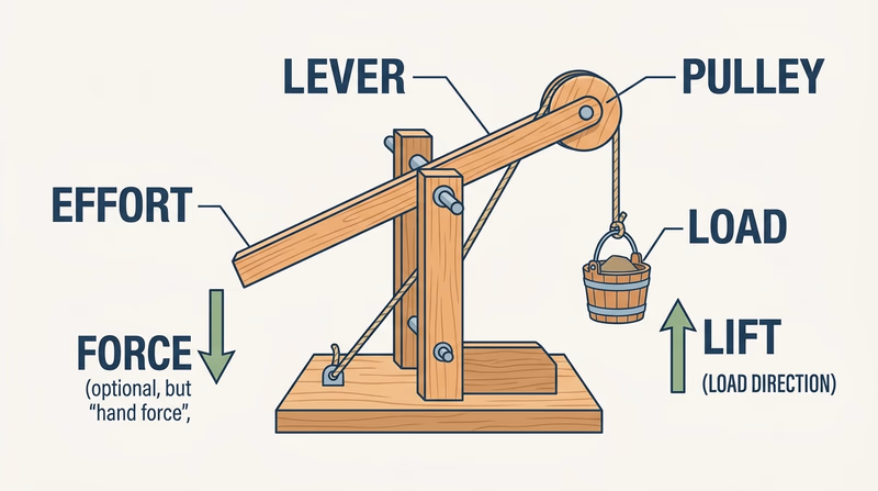
If you like shape and proportion more than moving parts, the industrial vehicle model lets you study a real object from every angle and turn it into a scaled design.